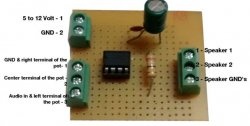
Now let's move on to the assembly and first get acquainted with the diagram.
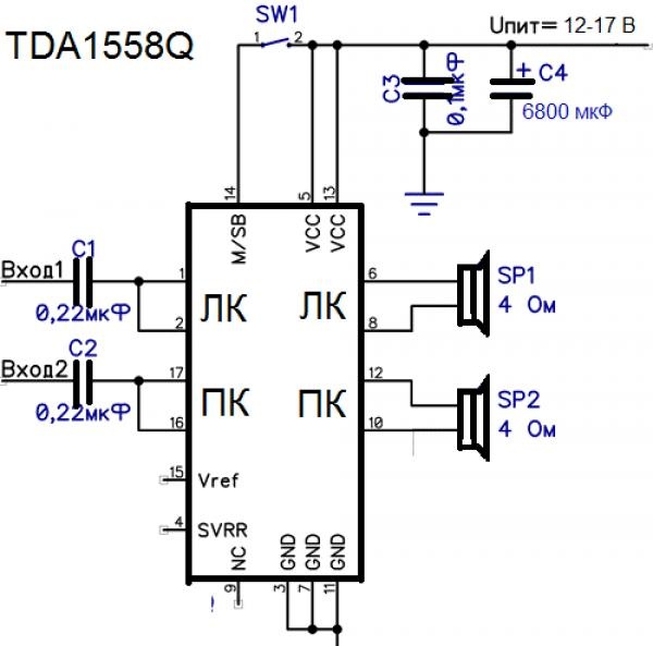
The circuit is extremely simple and can be assembled in 10-15 minutes; its simplicity allows it to be soldered by overhead mounting. It is also worth recalling that the circuit has the thermal characteristics of an iron and requires a radiator of approximately 600 cm2 in area and either an open case or forced cooling in the form of a fan.
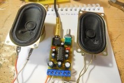
Here is the set of parts that I needed to assemble the amplifier.
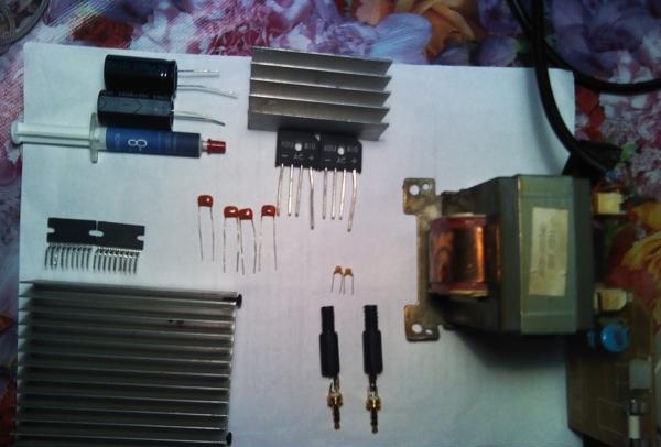
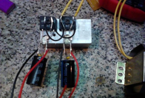
I used two diode bridges because I used a transformer with two similar windings; usually one 8 A is enough.
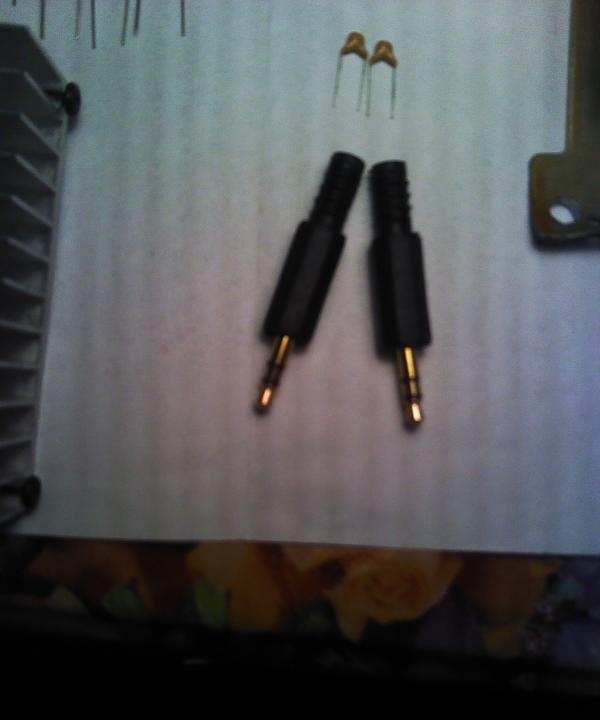
Two 3.5 plugs were purchased separately for inclusion in a computer audio card.
Now I think we can move on to actually assembling the amplifier. I didn’t have a ready-made power supply and I had to assemble it myself, and I recommend that you do the same since it’s not easy to find ready-made power supplies with the necessary power reserve since at a voltage of 17 V one microcircuit consumes about 3 A even when “silent”. Also, if you disconnect the 14th pin, the amplifier will go into “Sleep mode” and the current consumption will be reduced to a couple of hundred mA
And so, first, we will find a transformer of the required power, then you can solder the rectifier yourself, but I still advise you to take a ready-made diode bridge. We take it and install it on a small radiator. (I didn't have a small one)
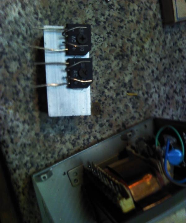
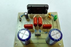
Then we solder the capacitors
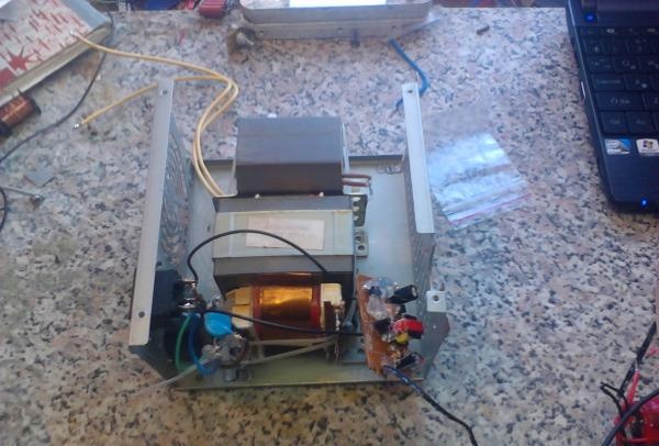
Since I also needed to install a transformer for another device, I decided to separate the power supply from the amplifier itself.
Since I used this amplifier for a home computer, I decided to “link” turning on the amplifier with turning on the computer; how to do this is described in this article (Automatically turn on and off from your computer) I didn’t go exactly the same way as in the article I connected the relay to the yellow and black (12 V) wires coming from the power supply of the system unit and brought a wire from it to the power supply of the amplifier. I would also like to say that the higher the voltage, the better the sound at high volume, but accordingly the heating also increases, the optimal supply voltage is 15 V, when the threshold of 17 volts is exceeded, the amplifier goes silent (While the voltage is exceeded) so if there is no sound, measure the voltage.
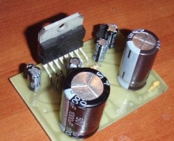
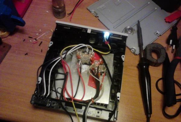
Now let's move on to assembling the amplifier itself. Since the circuit for connecting the microcircuit is primitive and probably couldn’t be simpler, I decided to solder everything by surface mounting.
To begin with, we attach the microcircuits to the radiator; it is first recommended to coat the connection point with thermal paste
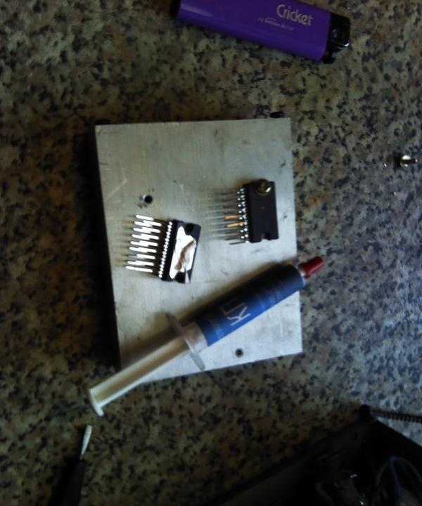
After this, looking at the diagram, we bend the necessary contacts (14, 5, 13 - Plus power supply. 3, 7, 11 - Minus power supply. Etc.) You can bite off the excess contacts so that they do not get in the way.
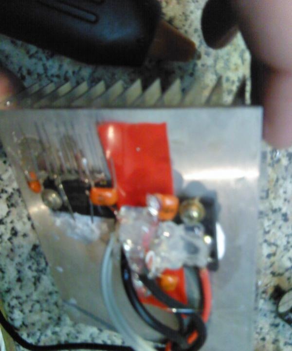
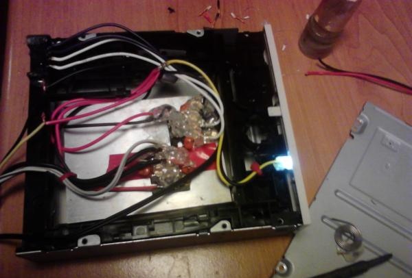
After you have soldered all the necessary wires and capacitors, you need to get rid of the unreliable “fragility” (for wall-mounted installation), I recommend using hot-melt adhesive to carefully fill the contacts in such a way as to avoid a short circuit between them.
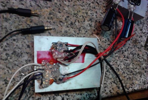
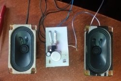
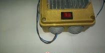
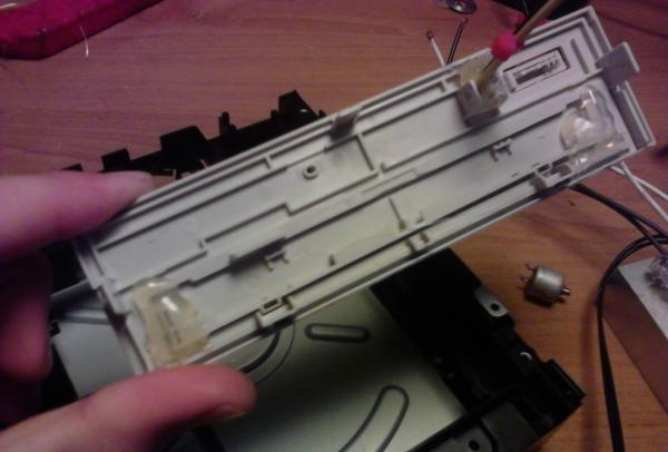
In essence, the amplifier as such is ready, i.e. he can already fully function. But I seriously doubt that anyone will be ready to decorate their desk with such a piece of hardware. And therefore a case is needed, it all depends on your imagination, I just took the case from a broken disk drive.
To begin with, I used the same hot glue to secure the plug from the disk tray and glued my Light-emitting diode.
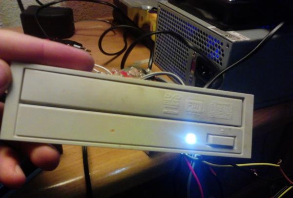
To connect Light-emitting diode to the 12V power supply it is necessary to connect a resistance of 500...900 Ohm in series (Depending on the power)
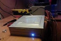
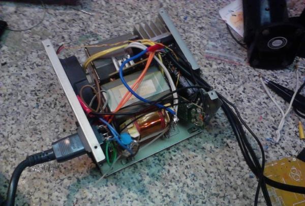
Then we put everything into the case and take out the wires
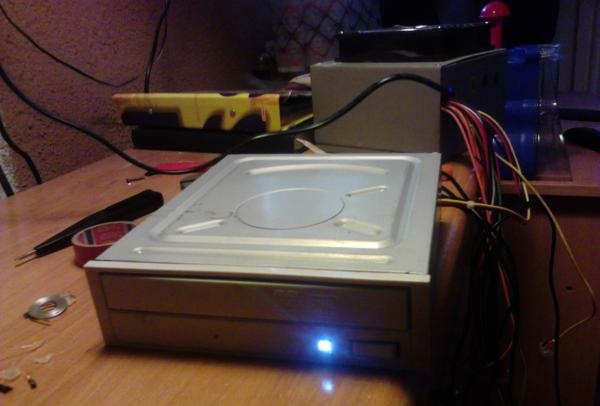
If you use such a case, you can attach the microcircuits directly to the metal case (inside), then the case will serve as a radiator. But I went the other way, I made ventilation holes and installed a small fan.
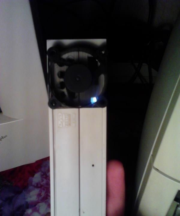
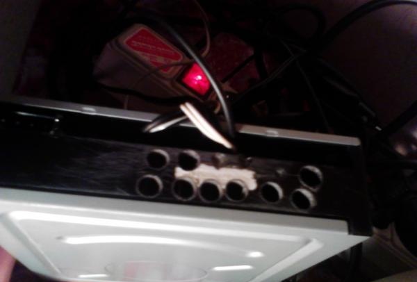
This is quite enough to prevent the amplifier from overheating.
The amplifier is ready. I did not install volume and balance controls for the reason that now even the most budget audio cards are equipped with excellent software for these purposes.
If we talk about the price, then everything here is not very expensive.
1. TDA1558Q microcircuits – 80 rub. 1 PC.
2. Capacitors (0.22 uF 4 pcs. 0.1 uF 2 pcs.) 35 rub. for all
3. Capacitor 25V 6800uF 38 rub. 1 PC.
4. Thermal paste 40 rub.
5. Diode bridge 1000V 8A 20 rub.
Everything was purchased in specialized radio market stores.
Good luck to those wishing to repeat!