There are a lot of voltage converter circuits, but as a rule, after assembly, defects, malfunctions, and incomprehensible overheating of individual parts and parts of the circuit appear. Assembling the converter took me two weeks, since a number of changes were made to the main circuit; in the end, I can safely say that the result was a powerful and reliable converter.
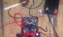
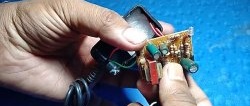
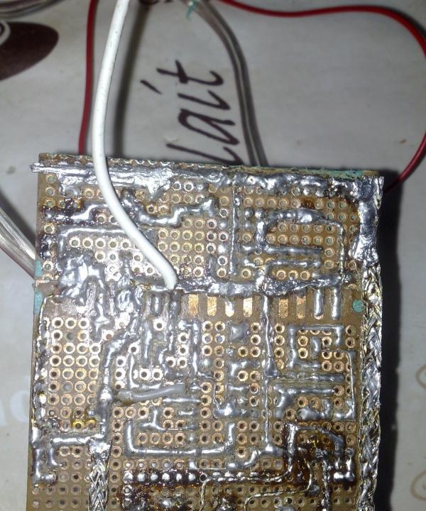
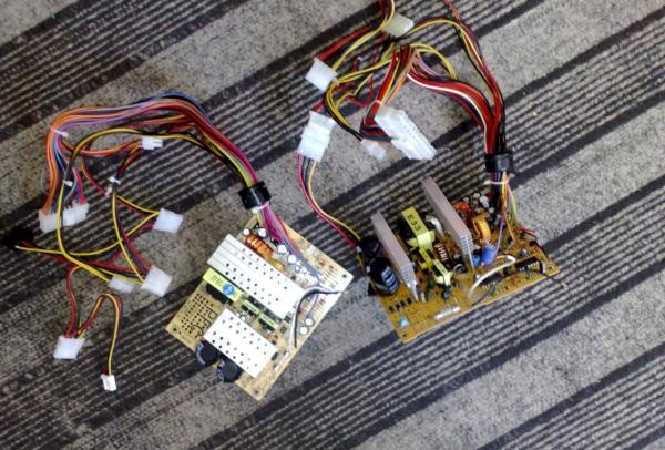
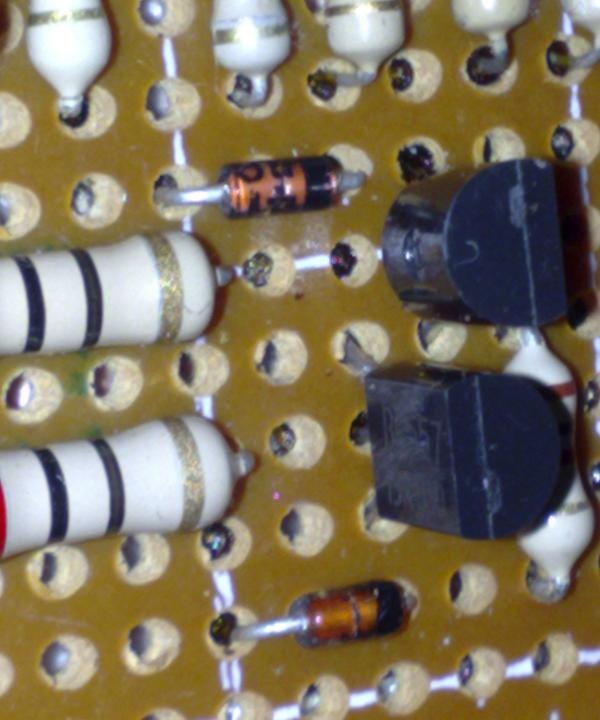
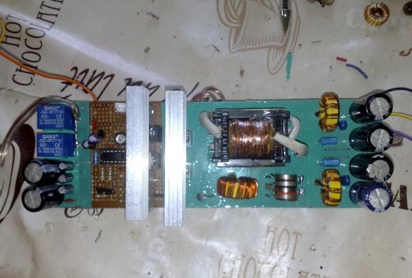
The main task was to build a 300-350 watt converter to power the amplifier according to the Lanzar scheme, everything turned out beautifully and neatly, everything except the board, we have a big shortage of chemicals for etching boards, so we had to use a breadboard, but I don’t advise repeating my torment, soldering Wiring for each track, tinning each hole and contact is not an easy job, this can be judged by looking at the back of the board. For a beautiful appearance, wide green tape was glued to the board.
PULSE TRANSFORMER
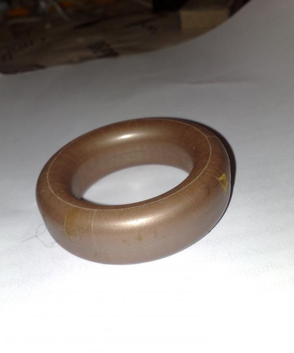
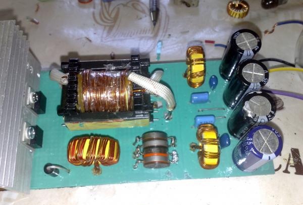
The main change in the circuit is the pulse transformer. In almost all articles on homemade subwoofer installations, the transformer is made on ferrite rings, but the rings are sometimes not available (as in my case). The only thing that was there was an Alsifer ring from a high-frequency choke, but the operating frequency of this ring did not allow it to be used as a transformer in a voltage converter.
Here I was lucky, I received a couple of computer power supplies almost for nothing; fortunately, both units had completely identical transformers.
As a result, it was decided to use two transformers as one, although one such transformer can provide the desired power, but when winding the windings simply would not fit, so it was decided to remake both transformers.
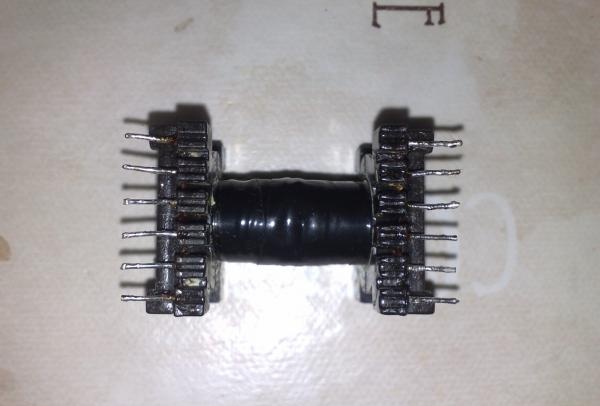
First, you need to remove the heart; in fact, the work is quite simple. Using a lighter, we heat the ferrite stick, which closes the main heart, and after 30 seconds of heating, the glue melts and the ferrite stick falls out. The properties of the stick may change due to overheating, but this is not so important, since we will not use sticks in the main transformer.
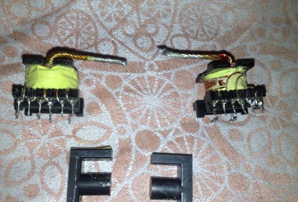
We do the same with the second transformer, then we remove all the standard windings, clean the transformer terminals and cut off one of the side walls of both transformers, it is advisable to cut down the wall free from contacts.
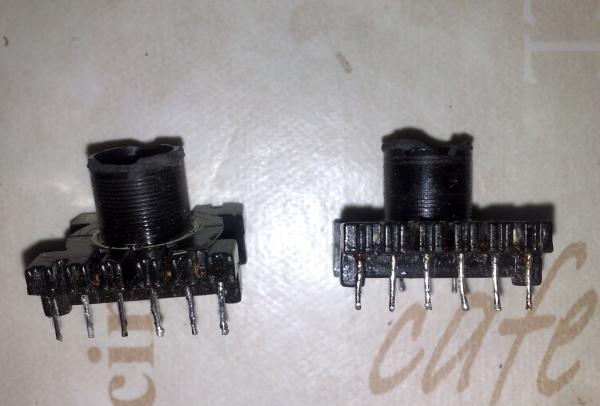
The next part of the work is gluing the frames. You can simply wrap the fastening area (seam) with electrical tape or tape; I do not recommend using various adhesives, as this may interfere with the insertion of the core.
I had experience in assembling voltage converters, but nevertheless this converter took all the juice and money from me, since during the work 8 field workers were killed and the transformer was to blame for everything.
Experiments with the number of turns, winding technology and wire cross-sections led to pleasing results.
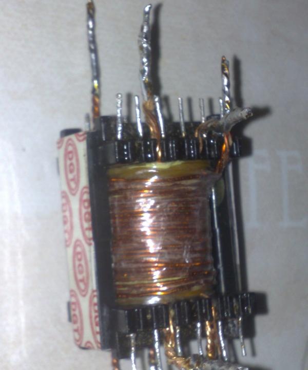
So the hardest part is winding. Many forums advise winding a thick primary, but experience has shown that you don’t need much to get the specified power. The primary winding consists of two completely identical windings, each of them is wound with 5 strands of 0.8 mm wire, stretched along the entire length of the frame, but we won’t rush. To begin with, we take a wire with a diameter of 0.8 mm, the wire is preferably new and smooth, without bends (although I used a wire from the network winding of the same transformers from power supplies).
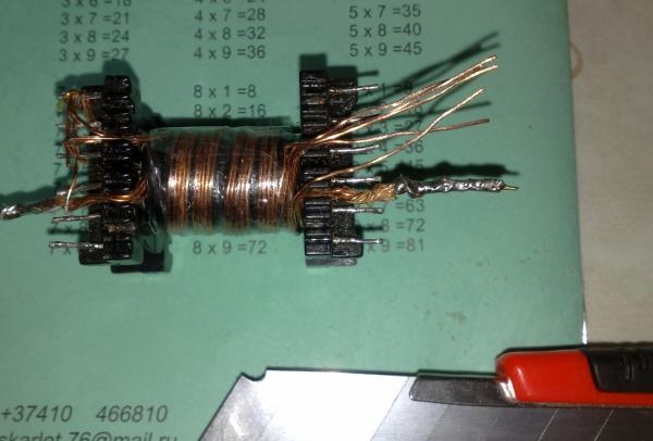
Next, we wind 5 turns along one wire along the entire length of the transformer frame (you can also wind all the wires together with a bundle). After winding the first core, it needs to be strengthened by simply winding it onto the side terminals of the transformer. Afterwards we wind the rest of the wires, evenly and neatly. After winding is completed, you need to get rid of the varnish coating on the ends of the winding; this can be done in several ways - heat the wires with a powerful soldering iron or remove the varnish individually from each wire with a mounting knife or razor.After this, you need to tin the ends of the wires, weave them into a pigtail (it’s convenient to use pliers) and cover them with a thick layer of tin.
After this, we move on to the second half of the primary winding. It is completely identical to the first one; before winding it, we cover the first part of the winding with electrical tape. The second half of the primary winding is also stretched across the entire frame and wound in the same direction as the first; we wind it according to the same principle, one core at a time.
After winding is completed, the windings need to be phased. We should get one winding, which consists of 10 turns and has a tap from the middle. It is important to remember one important detail here - the end of the first half should join with the beginning of the second half or vice versa, so that there are no difficulties with phasing, it is better to do everything from photographs.
After a lot of hard work, the primary winding is finally ready! (you can drink beer).
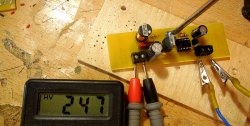
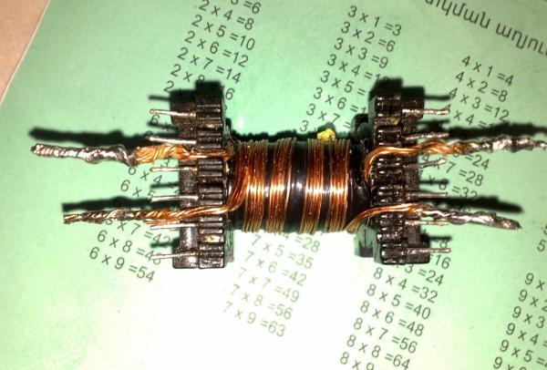
The secondary winding also requires a lot of attention, since it is this that will power the amplifier. It is wound according to the same principle as the primary, only each half consists of 12 turns, which fully provides a bipolar output voltage of 50-55 volts.
The winding consists of two halves, each is wound with 3 strands of 0.8 mm wire, the wires are stretched throughout the frame. After winding the first half, we insulate the winding and wind the second half on top in the same direction as the first. As a result, we get two identical halves, which are phased in the same way as the primary. Afterwards, the leads are cleaned, intertwined and sealed to each other.
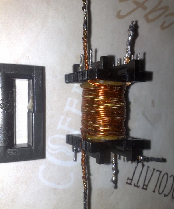
One important point - if you decide to use other types of transformers, then make sure that the halves of the heart do not have a gap; as a result of experiments, it was found that even the slightest gap of 0.1 mm sharply disrupts the operation of the circuit, the current consumption increases by 3-4 times , the field-effect transistors begin to overheat so that the cooler does not have time to cool them.
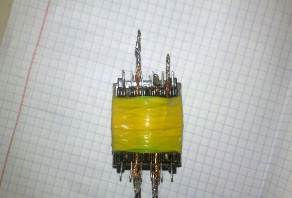
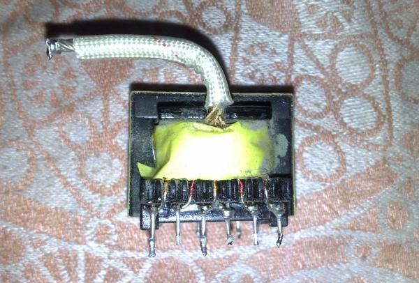
The finished transformer can be shielded with copper foil, but this does not play a particularly big role.
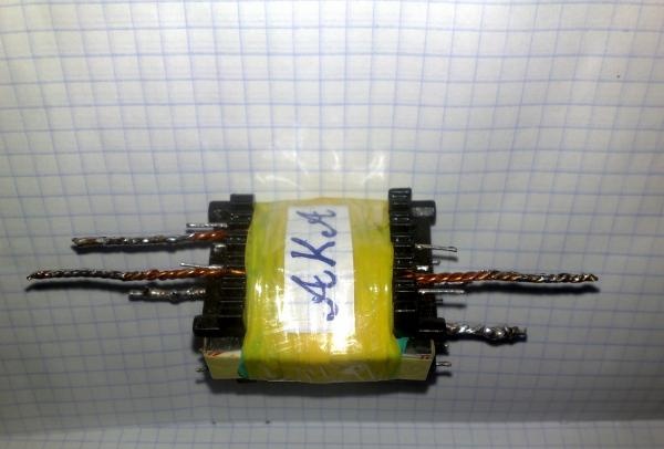
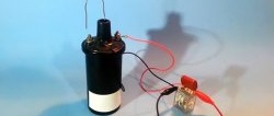
The result is a compact transformer that can easily deliver the required power.
SCHEME
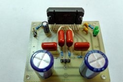
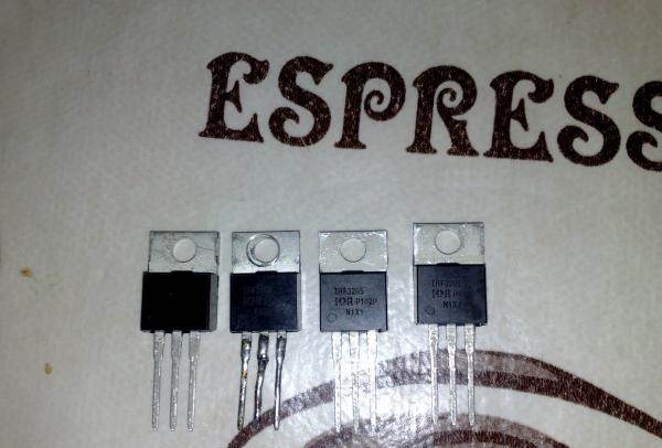
The circuit diagram of the device is not simple; I do not advise novice radio amateurs to contact it. The basis, as always, is a pulse generator built on the TL494 integrated circuit. The additional output amplifier is built on a pair of low-power transistors of the BC 557 series, almost a complete analogue of the BC556; from the domestic interior, you can use the KT3107. Two pairs of powerful field-effect transistors of the IRF3205 series are used as power switches, 2 field-effect transistors per arm.
The transistors are installed on small heat sinks from computer power supplies and are pre-insulated from the heat sink with a special gasket.
The 51 ohm resistor is the only part of the circuit that overheats, so a 2-watt resistor is needed (although I only have 1 watt), but overheating is not terrible, it does not affect the operation of the circuit in any way.
Installation, especially on a breadboard, is a very tedious process, so it’s better to do everything on a printed circuit board. We make the plus and minus tracks wider, then cover them with thick layers of tin, since a considerable current will flow through them, the same with the field drains.
We set 22 ohm resistors at 0.5-1 watt, they are designed to remove overload from the microcircuit.
The field gate current limiting resistors and the microcircuit supply current limiting resistor (10 ohm) are preferably half a watt, all other resistors can be 0.125 watt.
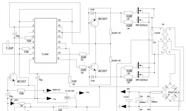
The frequency of the converter is set using a 1.2nf capacitor and a 15k resistor; by decreasing the capacitance of the capacitor and increasing the resistance of the resistor, you can increase the frequency or vice versa, but it is advisable not to play with the frequency, since the operation of the entire circuit may be disrupted.
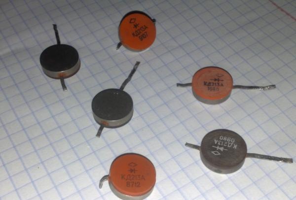
The rectifier diodes were used in the KD213A series; they did the best job, because due to the operating frequency (100 kHz) they felt excellent, although you can use any high-speed diodes with a current of at least 10 amperes; it is also possible to use Schottky diode assemblies, which can be found in the same computer power supplies, in one case there are 2 diodes that have a common cathode, so for a diode bridge you will need 3 such diode assemblies. Another diode is installed to power the circuit; this diode serves as protection against power overload.
Unfortunately, I have capacitors with a voltage of 35 volts of 3300 microfarads, but it is better to select a voltage from 50 to 63 volts. There are two such capacitors per arm.
The circuit uses 3 chokes, the first to power the converter circuit. This choke can be wound on standard yellow rings from power supplies. We wind 10 turns evenly around the entire ring, the wire is divided into two 1 mm wires.
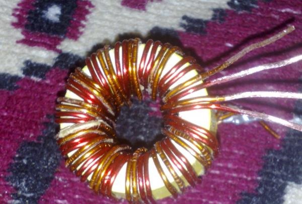
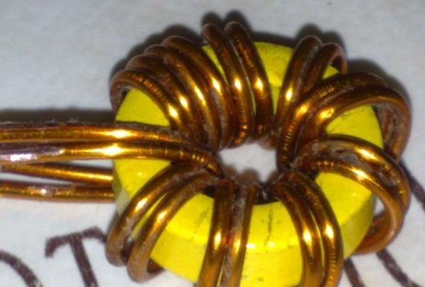
Chokes for filtering RF interference after the transformer also contain 10 turns, wire with a diameter of 1-1.5 mm, wound on the same rings or on ferrite rods of any brand (the diameter of the rods is not critical, length 2-4 cm).
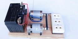
The converter is powered when the Remote Control (REM) wire is connected to the power supply positive, this closes the relay and the converter starts working. I used two relays connected in parallel at 25 amps each.

The coolers are soldered onto the converter block and turn on immediately after the REM wire is turned on. One of them is designed to cool the converter, the other is for the amplifier, you can also install one of the coolers in the opposite direction so that the latter removes warm air from the common case.
RESULTS AND COSTS
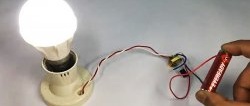
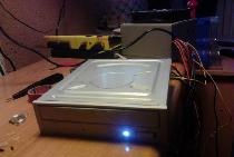
Well, what can I say, the converter justified all hopes and costs, it works like a clock. As a result of the experiments, he was able to deliver an honest 500 watts and would have been able to do more if the diode bridge of the unit that powered the converter had not died.
Total spent on the converter (prices shown are for the total number of parts, not for one)
- IRF3205 4pcs - 5$
- TL494 1pc -0.5$
- BC557 3pcs - 1$
- KD213A 4pcs - 4$
- Capacitors 35V 3300uF 4pcs - $3
- Resistor 51 ohm 1 piece - $0.1
- Resistor 22 ohm 2 pcs -0.15$
- Development board - $1
From this list, I got the diodes and capacitors for free, I think except for the field workers and the microcircuit, everything can be found in the attic, asked from friends or in workshops, so the price of the converter does not exceed $10. You can buy a ready-made Chinese amplifier for a subwoofer with all the amenities for $80-100, and products from well-known companies cost a lot, from $300 to $1000. In return, you can assemble an amplifier of identical quality for only $50-60, even less if you know where to get the parts from , I hope I was able to answer many questions.
AKA KASYAN