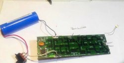
The circuit is designed to control current, voltage and optically indicate that the lithium-ion battery has reached full charge and is included in the gap between a voltage source of 6 to 12 V and the battery being charged. The state of charge is indicated by a luminous Light-emitting diode, when fully charged Light-emitting diode goes out.
The indicator is characterized by circuit simplicity and is assembled from electronic components widely available in the trade.
Indicator circuit
The indicator diagram is shown below:
The battery being charged is connected to the Output “-” and Output “+” terminals, a direct current source (its functions can be performed by any battery with an output voltage of 6 to 12 V or a network source) – to the Input “-” and Input “+” terminals. respectively.
An undercharged battery has a voltage of less than 4.2 V at its terminals and is charged by a current that flows from the source through a 47 Ohm resistor and the collector junction of power transistor T1.In this case, the potential present at the connection point of the 1 kOhm and 680 Ohm resistors opens the zener diode Vd1 and through the indicator Light-emitting diode a current begins to flow, which causes it to glow.
When the battery voltage reaches 4.2 V, which corresponds to its full charge, the zener diode closes, the current through Light-emitting diode stops, the latter goes out and marks the completion of the charging procedure.
Element base
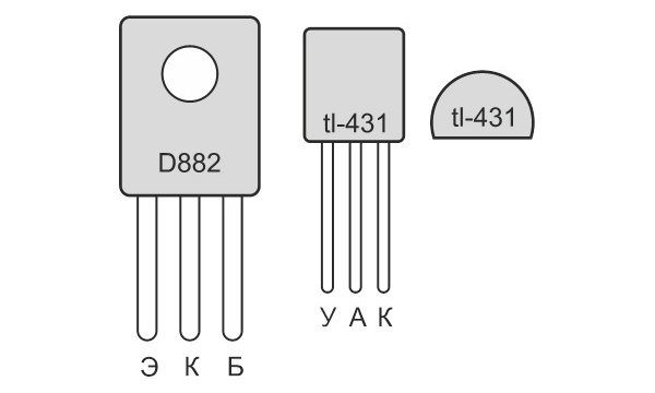
To implement the indicator you will need:- any indicator Light-emitting diode with forward current up to 50 mA - http://alii.pub/5lag4f
- powerful bipolar transistor D882 with an NPN structure in a plastic case or its quite numerous imported analogues - http://alii.pub/5vunm9
- controlled integrated zener diode TL431 in TO92 housing - http://alii.pub/5mclsi
- three resistors with a nominal value of 47 Ohm, 680 Ohm and 1 kOhm with a power dissipation of 0.25 W - http://alii.pub/5h6ouv
The pinout of the transistor and the controlled zener diode is shown in the sketch.
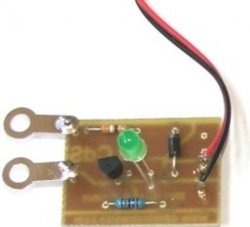
Installation and commissioning
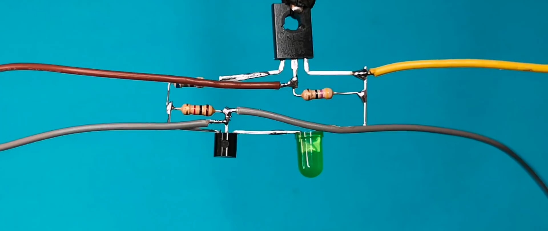
Taking into account the fairly high rigidity of the terminals of the power transistor D882 and the integrated zener diode tl431, as well as the relative simplicity of the circuit, the mandatory use of a printed circuit board or circuit board is not required. This allows you to assemble a circuit “on weight”, using a transistor and a zener diode as a supporting base.
The Input “-” and Output “-” terminals are circuit-connected; the use of different wires for their implementation is determined by considerations of ease of operation.
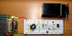
No special circuit adjustment is required.
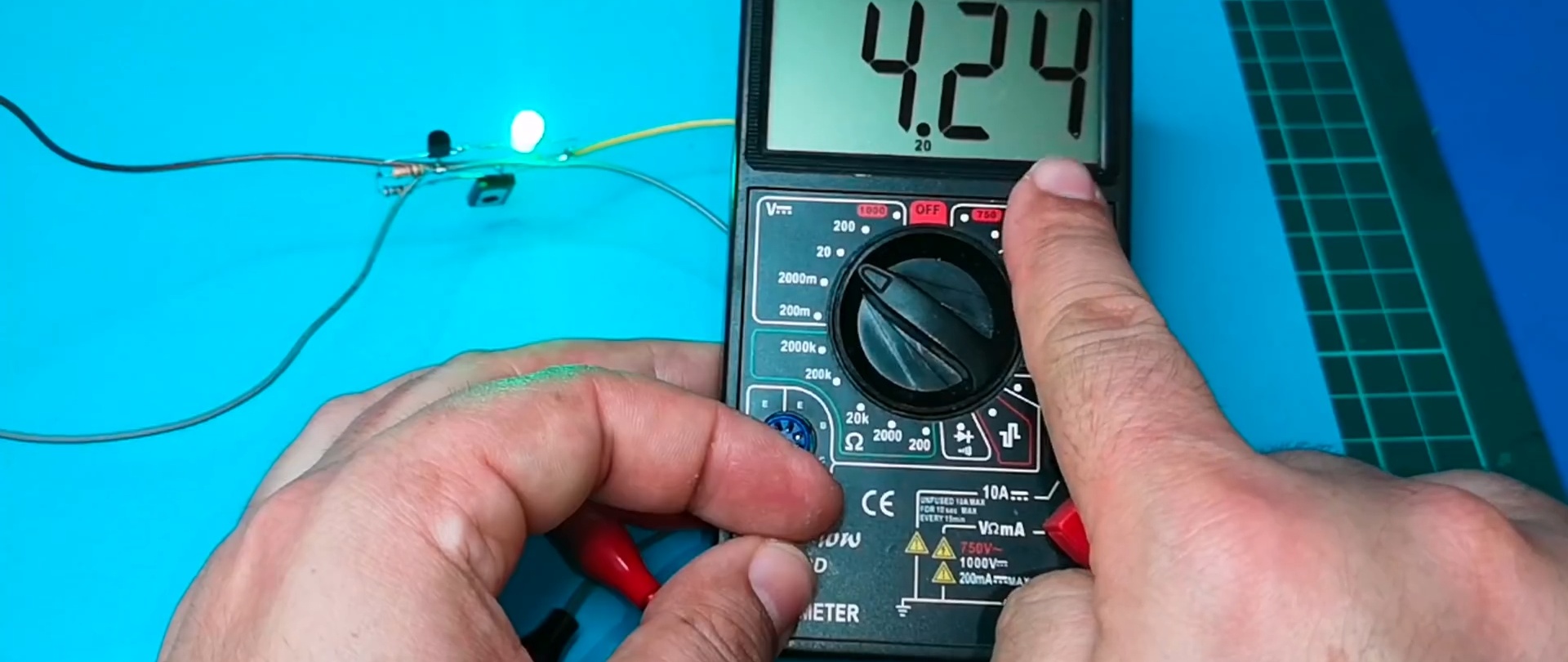
If connected to the output multimeter, then the output voltage is 4.2 V.
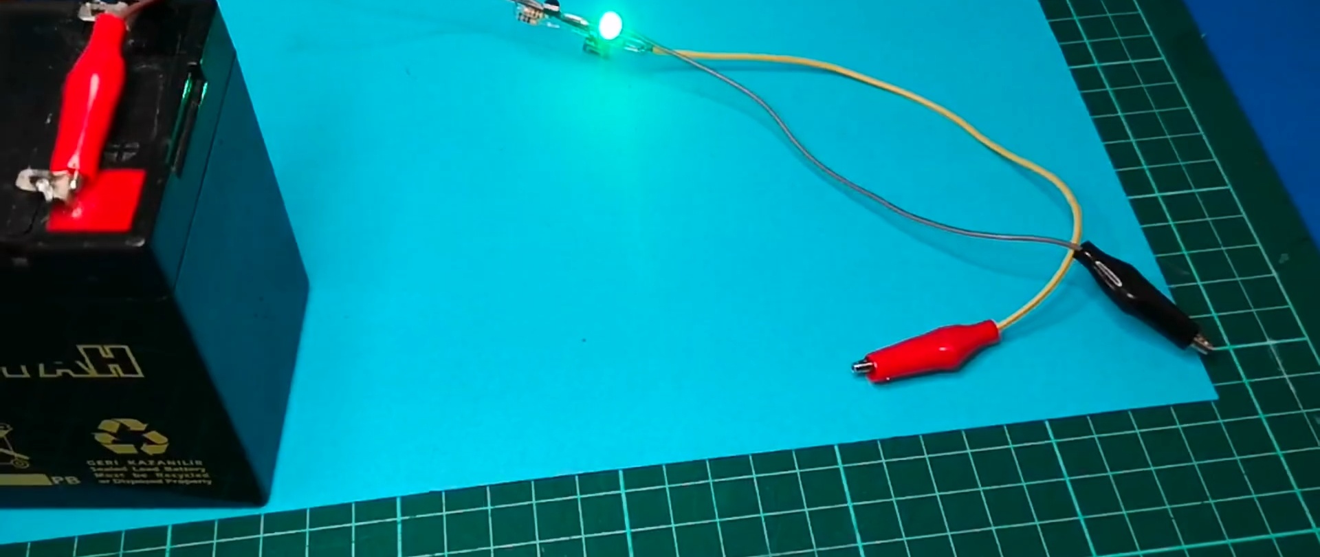
When connecting a discharged battery, the LED goes out.

And lights up after the battery is fully charged.