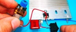
The DC circuit protection circuit is easy to assemble and does not require configuration. It is capable of not only monitoring a short circuit in the circuit, but also monitoring the voltage drop across the load. The device has an operation indication and a start button.
For assembly you will need the following parts:
- Operational amplifier LM358 -
- Stabilizer chip TL431 - http://alii.pub/5mclsi
- Tact button - http://alii.pub/5nnu8o
- Light-emitting diode - http://alii.pub/5lag4f
- Transistor IRFZ441N - http://alii.pub/5ct567
- Variable resistor 50 kOhm - http://alii.pub/5o27v2
- Resistors: 3 kOhm, 200 kOhm, 1 kOhm - 2 pieces - http://alii.pub/5h6ouv
Schematic diagram
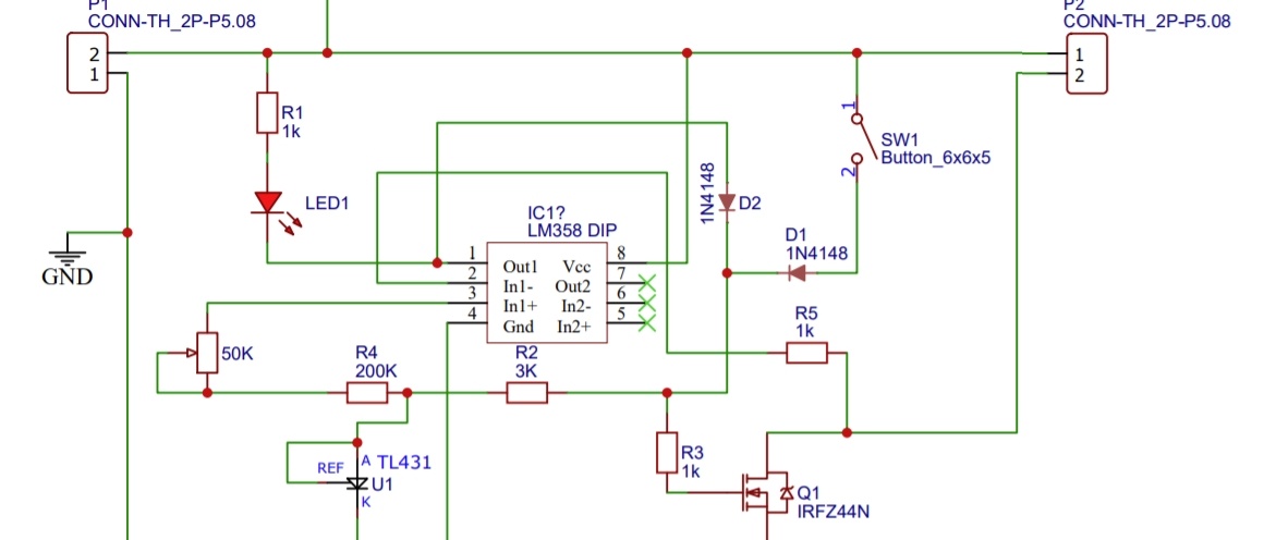
The protection device consists of a transistor switch that connects the load with the current source. The transistor, in turn, is controlled by an operational amplifier assembled on the LM358 chip, which takes data from the load and voltage regulator assembled on the TL431.
The response threshold is set by a variable resistor. As soon as the load voltage drops below the operating threshold, the operational amplifier closes the switch and the load is de-energized.
Manufacturing of short circuit protection device

The circuit is assembled by hanging installation. Thick metal conductors are used as power buses. On the left is the power input from the unit, on the right is the output to the load.
Testing and setting up
We connect the circuit to the circuit. An incandescent lamp is used as a load. The source is an adjustable DC source with a voltage of 5-15 V.
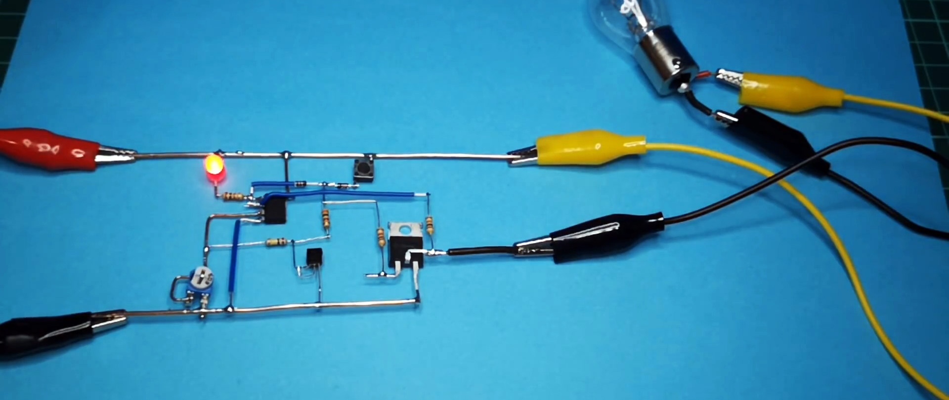
While the device is turned off - lights up Light-emitting diode. If you press the button and the lamp does not light up, then the threshold on the variable resistor is set too high. You need to take a screwdriver and set the desired one.

Now if you press the button, the light will light up. The scheme works. As soon as you close the lamp output, the device will immediately disconnect it from the power supply. And it will wait for the button to turn on again.

One useful circuit function
This circuit can not only operate protected from a short circuit, but also protected from excessive engine load. For clarity, let's connect a DC motor instead of an incandescent lamp. We press the button, the motor shaft rotates as it should.

Now, if you brake the motor shaft with your finger, the voltage in the circuit will “sag” and the device will turn off the motor, thereby protecting it and the power source.
This feature can be extremely useful for various purposes.