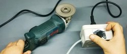
An electric engraver bought in a store at an average price usually comes with standard assembly and accessories; a housing with a motor, a collet or jaw chuck, and an AC power supply that matches the power consumption of the motor. A speed controller built into the engraver body is, of course, available, but such a model costs an order of magnitude more. In addition, in my opinion, the speed controller built into the body (usually a potentiometer with a round wheel) is not entirely convenient. You hold the engraver with one hand, the workpiece being processed with the other, you have to put the workpiece down to add or decrease the speed, and then aim again. You can, of course, get creative and turn the wheel with your free finger, but this is inconvenient and dangerous. In order to avoid this inconvenience, I decided to assemble a foot switch for my engravers.
One could say that this is a speed controller, but it turns the machine on and off - that means a switch. In addition, it will also have reverse. That is, the reverse move. Also sometimes a very necessary function.
Will need
- Drill start button, 7.2-24 V, 5-15 A
- DC plug and connector 5.5×2.1 mm
- Soldering iron with solder and flux.
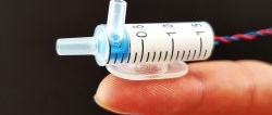
- Engraver with cutting disc and grinding head.
- Hot melt adhesive with a gun.
- Drill and 6mm drill bit.
- A bolt, 25-30 mm long, no more than 6 mm thick, and a nut for it.
- Metal profile, inch (25×25 mm), two sections - 80 mm and 110 mm.
- Phillips screwdriver.
- Ruler with marker.
- Insulating tape.
- Paint in a can (of the color you need).
- Electric copper wire, flexible, 12-30 V, 100 cm.

Making a foot switch
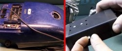
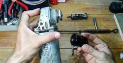
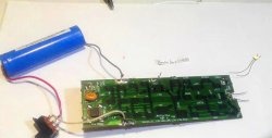
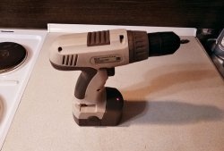
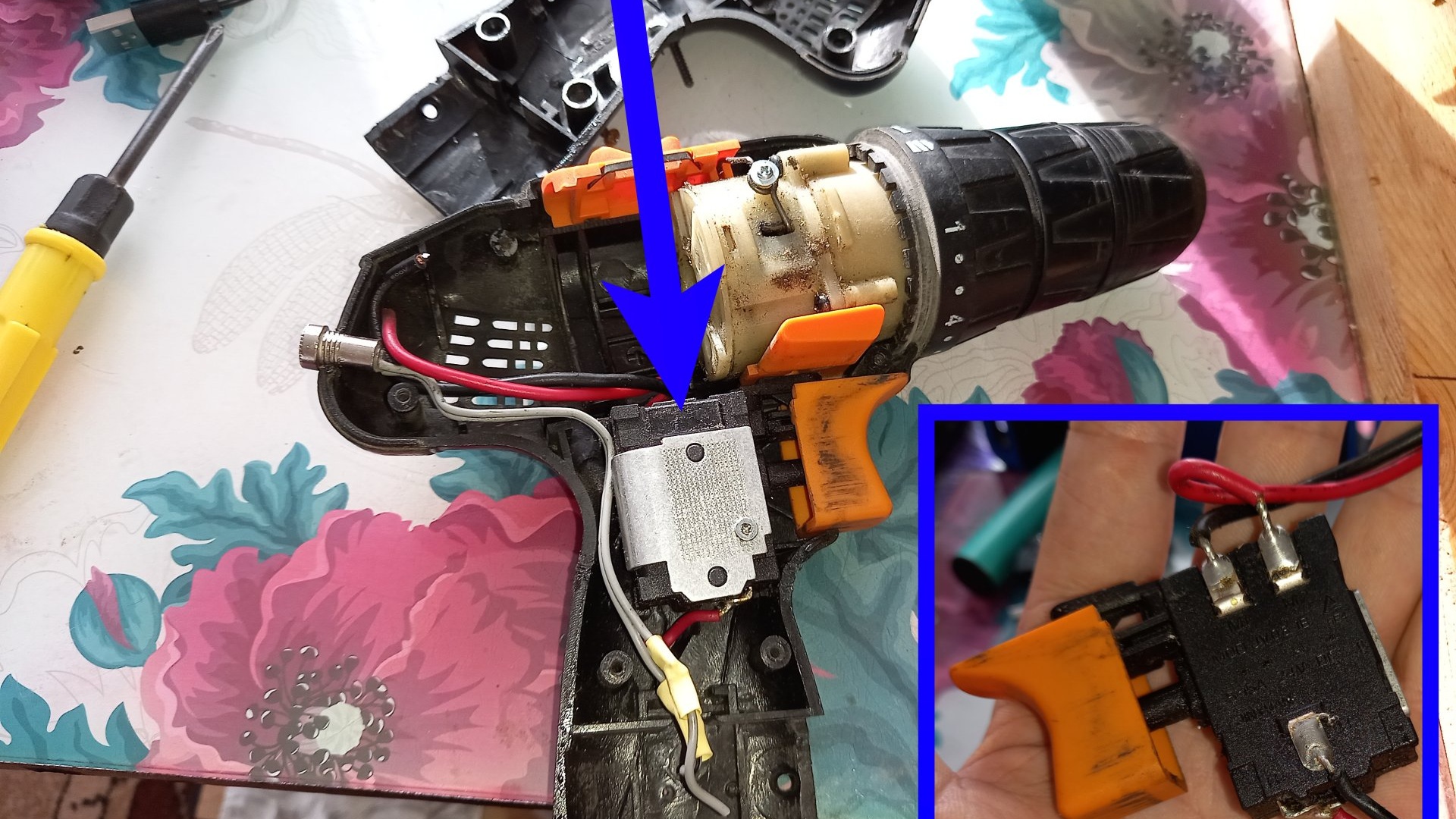
First, let's prepare the necessary tools and the necessary parts for the future switch. As a trigger mechanism, with speed control and reverse, I took a switch from an old, broken screwdriver.
You can purchase such a switch separately at a power tools store. It costs a penny. Next, let's prepare the body parts. For this purpose, I took two pieces of metal inch profile, 8 and 11 cm.
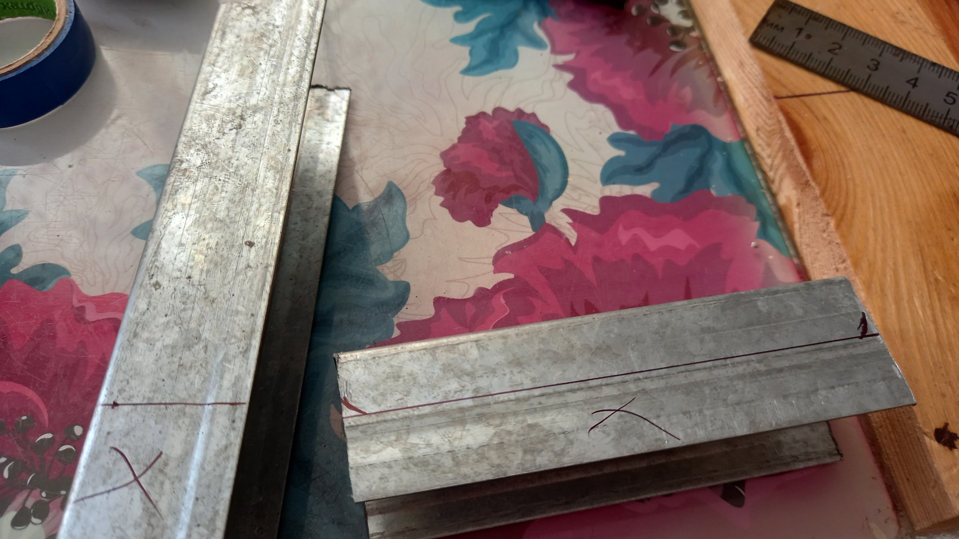
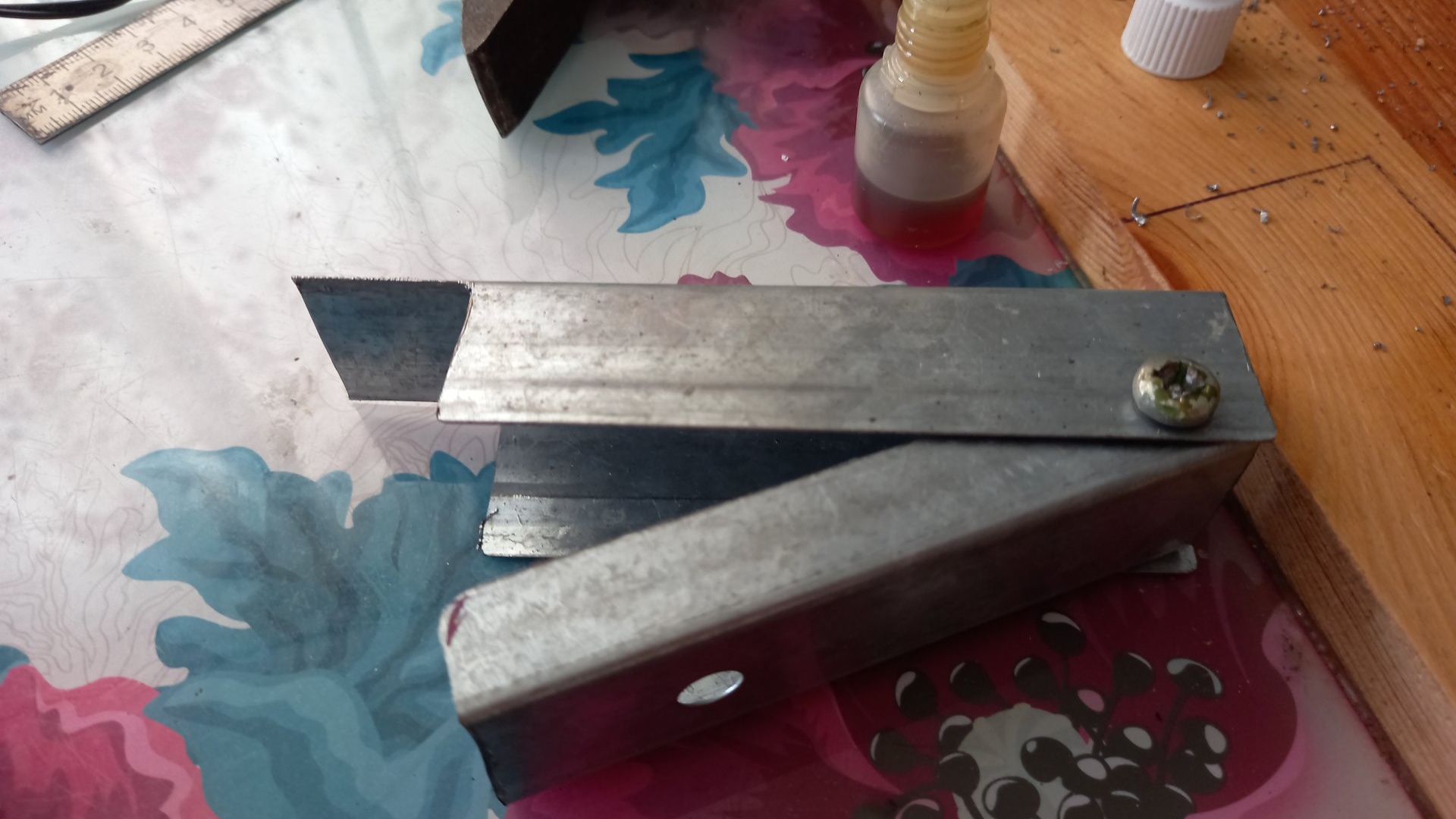
Now, for the shorter piece, we cut off one centimeter from each of the walls along the entire length, and for the longer piece, we retreat from one of the ends by 2.5 cm (1 inch - the width and height of the profile), and cut off both walls of the specified length, like this:
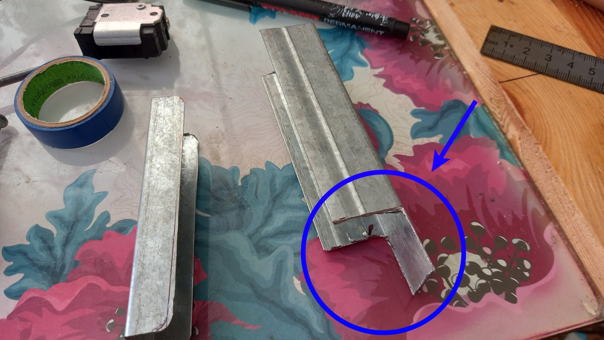
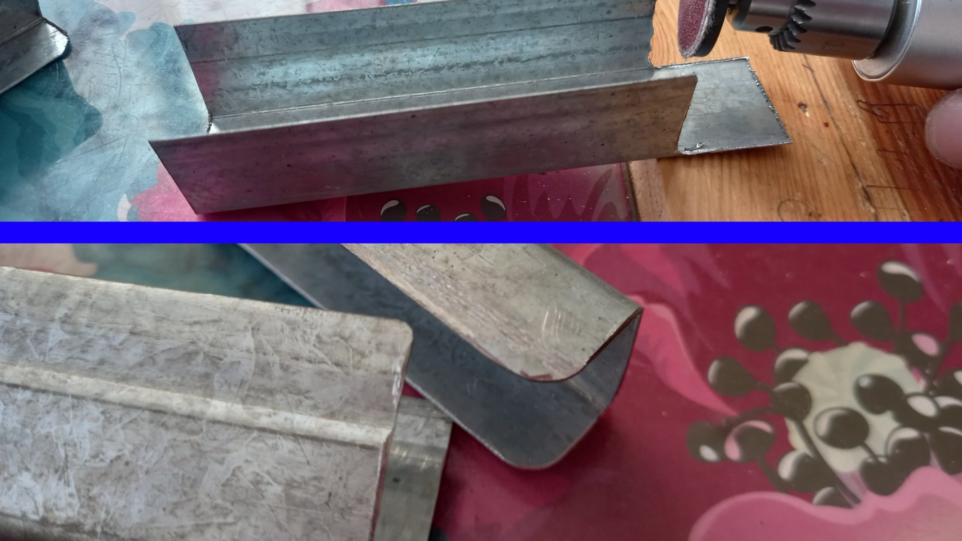
This is necessary in order to later bend the protruding remainder inward and get an end wall. To avoid injury, use a grinding head to carefully sand down all burrs after cutting and round the corners.
We put one part into the other, with the edges facing each other, align it, and drill a through hole.
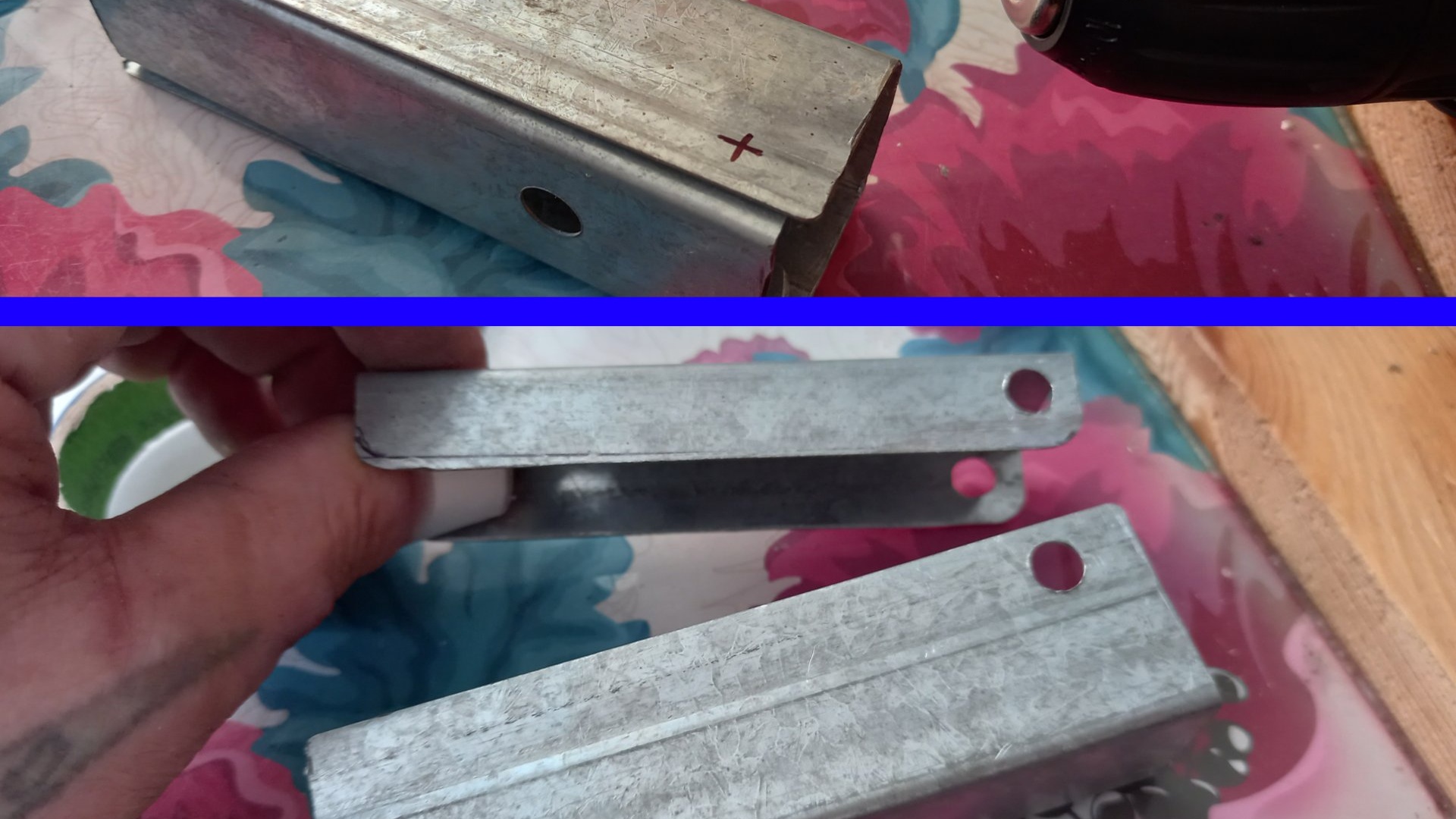
We thread a bolt into the hole, which will act as a hinge, and secure it on the opposite side with a nut.
We bend the protruding piece of the body inward, forming an end, and try on the switch inside.


Now it would be nice to paint the body.

Nitro paint from a can dries quite quickly, and while it dries, let's start soldering. The polarity designations, input and output, are usually indicated on the switch body, and all we can do is be more careful and not confuse anything.
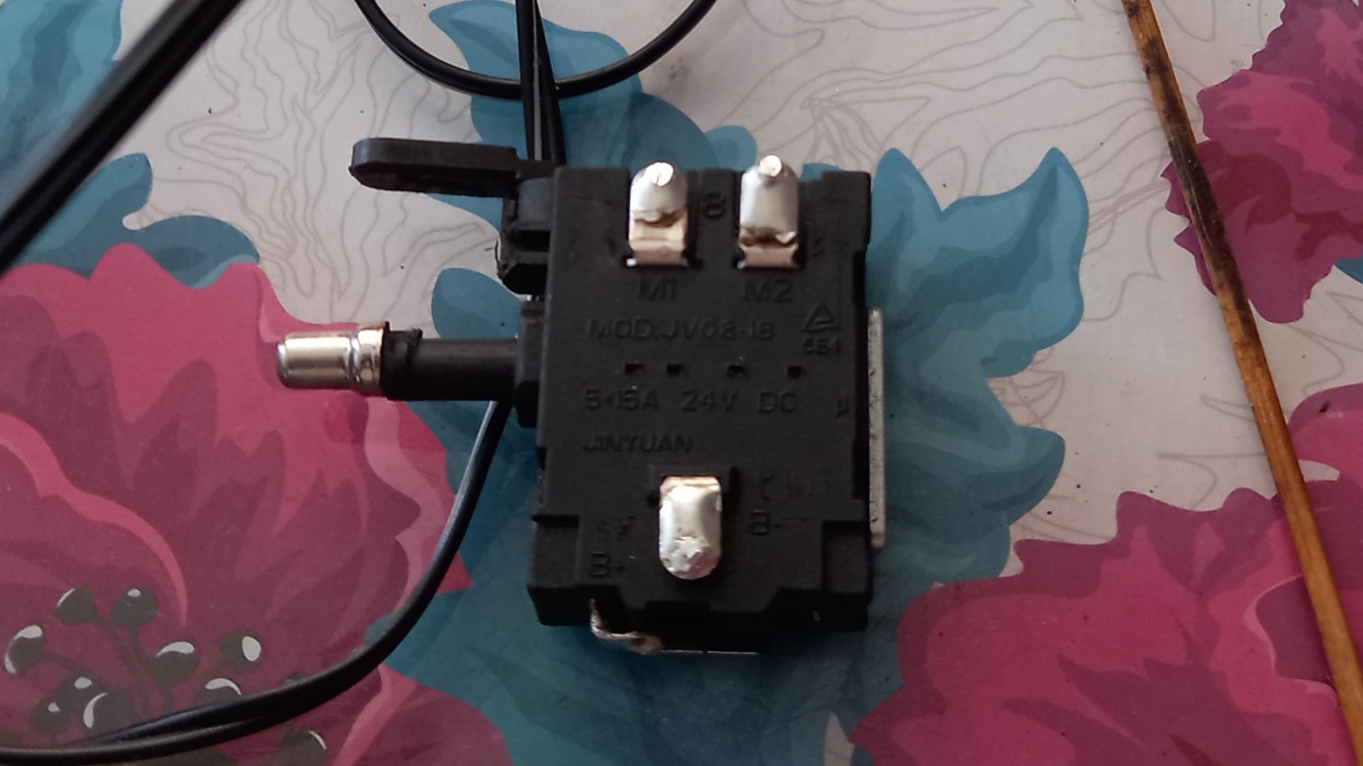
If these designations are not available, we will use a multimeter and calculate the polarity and purpose of the contacts ourselves. I think for those who have on the farm multimeter, no need to explain how to use it. So, solder the wires according to polarity.

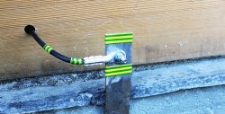
We solder the “mother” connector with a short wire to the input. Male plug to the output, on a long wire. On a connector and plug of this type, the internal contact always goes to positive, and the external contact to negative. After soldering, you need to check whether everything is soldered correctly.

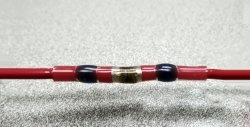
If everything is correct, we insulate all contacts with electrical tape.

If during soldering the paint on the body has had time to dry, then place the switch as close to the end as possible and secure it with hot glue.
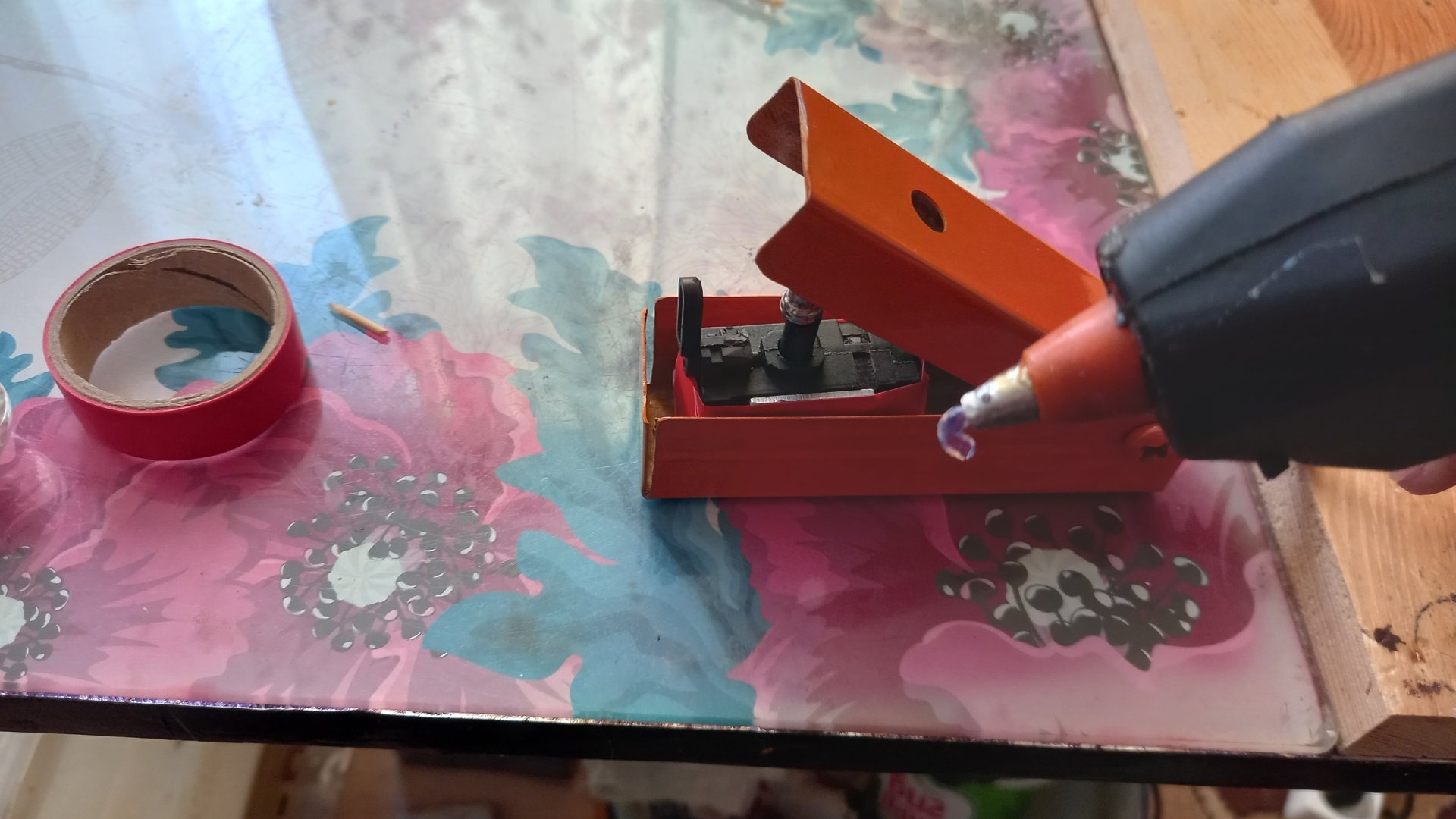
There is one subtle point here: the switch should be secured in the housing at an angle, like this:

That is, more glue should be squeezed out closer to the end so that there are no cavities left there. This angle is needed so that the pressure cover presses directly on the key with its entire plane, and does not press it casually. To make the hot melt glue stick to the metal better, you can slightly heat the metal with a lighter. Next, we thread the wires with the connector and plug through the rear end. The “female” connector, with a short wire, is also fastened with hot glue inside the case so that only the input itself sticks out.
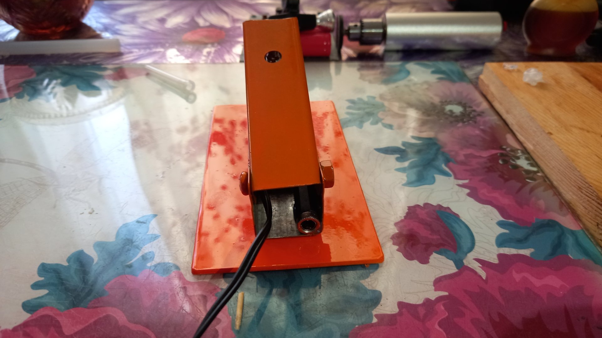
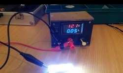
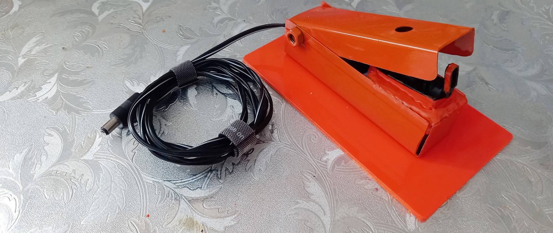
If the design of the switch does not seem stable enough to you, you can glue a small platform to its bottom. Now you can carry out a full check! With reverse switching and operation at different speeds.
Reverse in this case might seem unnecessary to someone in this product, but since the shift lever is provided in the design start button – then why not use it? And then, there are moments when, during work, sparks and scale inevitably fly into your face and eyes from the workpiece. This is where reverse comes in handy. Of course, there is an easier option to make a similar foot switch.

For example, use a button from a doorbell, 220 volts, as they were before. Modern doorbell buttons operating from 3 volts (two AA elements) will not withstand the voltage and current for the engraver (12-24 Volts, 2-4 Amperes), the contacts will get very hot and, as a result, the plastic case of the micro itself will melt keys, which will lead to failure of the entire button. And such a switch will not have a soft start, selection of the desired speed, or reverse.