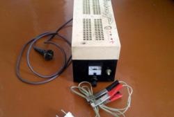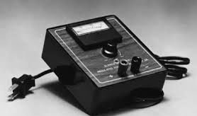
Hello! This is my first instruction! We are all surrounded by electrical appliances with different specifications. Most of them operate directly from a 220 V AC network. But what to do if you come up with some non-standard device, or are carrying out a project that requires a specific voltage, and also with direct current. Therefore, I had a desire to make a power supply that outputs different voltages and uses an lm317 voltage regulator on an integrated circuit.
What does a power supply do?
First you need to understand the purpose of the power source.
• It must convert the alternating current received from the AC power supply into direct current.
• It should output a user-selectable voltage ranging from 2V to 25V.
Main advantages:
• Inexpensive.
• Simple and easy to use.
• Versatile.
List of required components

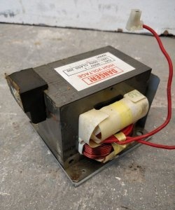
1. Step-down transformer 2 A (from 220 V to 24 V).
2. Voltage regulator lm317 IC with heat exchanger radiator.
3. Capacitors (polarized):
2200 microfarads 50 V;
100 microfarad 50 V;
1 microfarad 50 V.
(note: the voltage rating of the capacitors must be higher than the voltage applied to their contacts).
4. Capacitor (non-polarized): 0.1 microfarad.
5. Potentiometer 10 kOhm.
6. Resistance 1 kOhm.
7. Voltmeter with LCD display.
8. 2.5 A fuse.
9. Screw terminals.
10. Connecting wire with plug.
11. Diodes 1n5822.
12. Circuit board.
Drawing up an electrical diagram
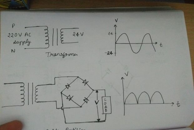
• In the upper part of the figure, the transformer is connected to the AC power supply. It reduces the voltage to 24 V, but the current remains alternating with a frequency of 50 Hz.
• The lower half of the figure shows the connection of four diodes into a rectifier bridge. 1n5822 diodes allow current to pass when forward biased, and block current to flow when reverse biased. As a result, the DC output voltage pulsates at a frequency of 100 Hz.
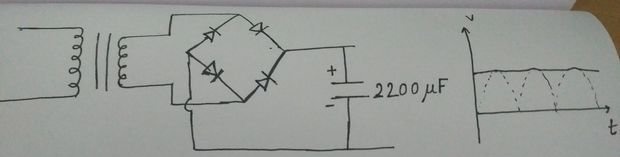
• In this figure, a 2200 microfarad capacitor has been added to filter the output current and provide a stable voltage of 24 VDC.
• At this point, a fuse can be connected in series with the circuit to ensure its protection.
• So we have:
1. AC step-down transformer up to 24 V.
2. Converter of alternating current to pulsating direct current with voltage up to 24 V.
3. Filtered current to produce a clean and stable 24V voltage.
• All this will be connected to the lm317 voltage regulator circuit described below
Introduction to Lm317
• Now our task is to control the output voltage, changing it according to our needs. For this we use a voltage regulator lm317.
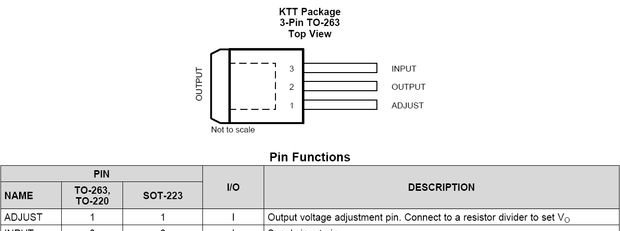
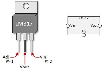
• Lm317 as shown in the picture has 3 pins.These are the adjustment pin (pin1 - ADJUST), the output pin (pin2 - OUNPUT), and the input pin (pin3 - INPUT).
• The lm317 regulator generates heat during operation, so it requires a heat exchanger radiator
• The heat exchanger heat sink is a metal plate connected to an integrated circuit to dissipate the heat it generates into the surrounding area.
Lm317 Wiring Diagram Explanation
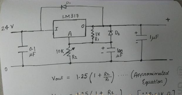
• This is a continuation of the previous electrical diagram. For better understanding, lm317 wiring diagram is shown here in detail.
• To ensure input filtering, it is recommended to use a 0.1 microfarad capacitor. It is very advisable not to place it near the main filter capacitor (in our case, this is a capacitor with a capacity of 2200 microfarads).
• The use of a 100 microfarad capacitor is recommended to improve ripple damping. It prevents the increase in ripples that occur when the set voltage increases.
• A 1 microfarad capacitor improves transient response but is not necessary for voltage regulation.
• Protection diodes D1 and D2 (both 1n5822) provide a low impedance discharge path, preventing the capacitor from discharging into the voltage regulator output.
• Resistors R1 and R2 are needed to set the output voltage
• The figure shows the control equation. Here the resistance R1 is 1 kΩ and the resistance R2 (potentiometer with a resistance of 10 kΩ) is variable. Therefore, the voltage obtained at the output, according to this approximated equation, is set by changing the resistance R2.
• If you need to obtain additional information on the characteristics of lm317 on an integrated circuit, find such information on the Internet.
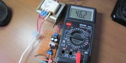
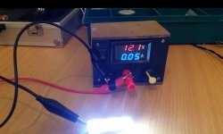
• Now the output voltage can be connected to an LCD voltmeter, or you can use multimeter for measuring voltage.
• Note: The values of resistances R1 and R2 are chosen for convenience. In other words, there is no hard and fast rule that says that R1 must always be 1k ohms and R2 must be variable up to 10k ohms. In addition, if you need a fixed output voltage, you can install a fixed resistance R2 instead of a variable one. Using the given control formula, you can choose the parameters R1 and R2 at your discretion.
Completing the electrical diagram
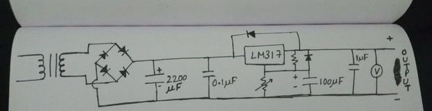
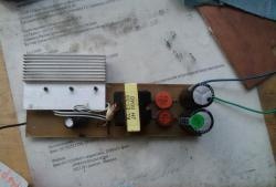
• The final electrical circuit looks like the one shown in the figure.
• Now, by using the potentiometer (i.e. R2), the required output voltage can be obtained.
• The output will be a clean, ripple-free, stable and constant voltage required to power the specific load.
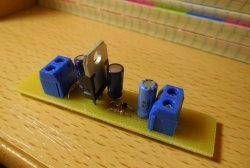
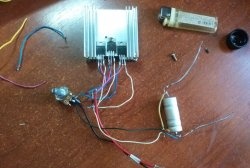
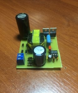
Soldering PCB
• This part of the work is done by hand.
• Make sure that all components are connected exactly as shown in the wiring diagram.
• Screw terminals are used at the input and output
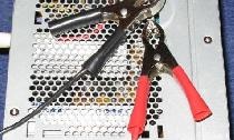
• Before connecting the manufactured power supply to the electrical network, you need to double check the circuit.
• For safety reasons, you must wear insulated or rubber shoes before connecting the device to the electrical network.
• If everything is done correctly, there is no possibility of any danger. However, all responsibility lies solely with you!
• The final circuit diagram is shown above. (I soldered the diodes from the back of the circuit board. Forgive me for the unprofessional soldering!).
Original article in English