One day it was necessary to check a prehistoric (Russian) remote control. There were no funds. After scouring the internet, I found a few ideas. I was amazed by the idea of making a simple IR port from a mouse! Computer, of course. We will start with this device.
1.IR port from a COM ball mouse.
Stunned by the idea, I went into the closet and dug up several ball mice, each older than the other. The older one had 6 wires coming from the computer, the newer one had four. He took it. The lines ran along four wires: RTS (Request To Send, a request to send. Used to power the mouse circuit.), Rx (through which the computer receives data), Tx (through which the computer transmits data), and of course GND, ground.
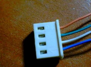
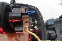
The photo shows the mouse wire plug. During the test, I found that the orange wire is RX, the green wire is TX, the white wire is RTS, and the blue wire is ground.
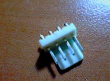
Next, for simplicity, I cut off a piece of plastic and glued the mouse pin connector onto it (the one that is soldered into the board):
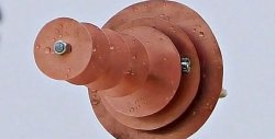
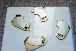
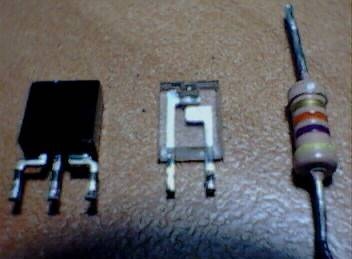
Then I removed the photodiode bridge and infrared from the same mouse Light-emitting diode. I took a 4.7 kOhm resistor from my supplies. The device to resistor is not critical - you can set it from 2 to 7 kOhm, but with a lower resistance the operating radius of the receiver decreases.Here's what the parts look like (from left to right: photodiode bridge, IR Light-emitting diode, resistor):
Here is the diagram of the device:
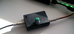
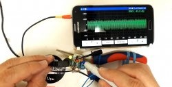
After half an hour of soldering and gluing, this is what happened:
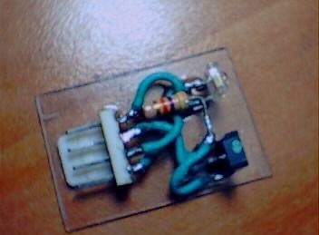
The device came out working - a reliable reception radius - 5 cm, transmission - 20 cm. This turned out to be enough to check the remote control: it doesn’t work.
2. Advanced IR transceiver device.
Since we've already run away, we need to talk about a more advanced device.
The port consists of a receiver (TSOP chip and body kit) and a transmitter (Light-emitting diode HL1 and current limiting resistor R2).
The receiver uses a specialized TSOPXXXX chip. It receives a signal with a certain frequency. This achieves high noise immunity. Since they are available in several versions - for different signal filtering frequencies, you need to choose the one you need for a specific remote control. Let's look at the datasheet:
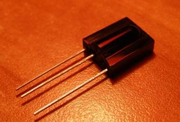
As you can see, there is a choice: from 30 to 56 kilohertz. The datasheet says that the maximum speed of the received signal is 2400 baud/sec, so it is difficult to judge whether the microphone will work, for example, with a mobile phone. This is what TSOP1736 looks like:
Resistor R1 pulls the RX line to power (after all, all COM port signals are inverted), diode VD1 protects the circuit from polarity reversal during port initialization, and capacitor C1 protects the receiver from interference. Well, the 7805 stabilizer, of course, adjusts the voltage to the IR receiver. I advise you to install it in a TO-92 case - it is smaller in size.
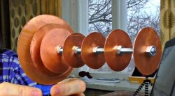
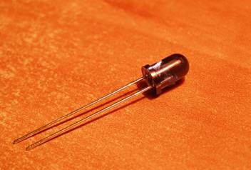
The transmitter is not particularly advanced; it differs only in a more powerful IR diode. You can put, for example, L-34F3C, L-54F3C. Resistor R2 limits the current through the diode. The IR diode looks like this:
This device receives and transmits well at a distance of up to 5 m.
If you want to experiment, here is the COM port pinout, widespread on the Internet:
3.Programs for working with IR ports.
Now let's talk about programs. I used the WinLirc program to check. The device showed pretty good results: reception radius was 5 cm, transmission radius was 20 cm maximum. It all depends on the type of photocells. As an example, I will give an example of working with a remote control from a music center.
Let's talk about setup.
Launch VinLIRC. She writes: configuration failed, reconfigure. Type the path and name of the configuration file in the Path field and then follow these steps: (note: these settings are only for this device):
1. In the Port field, put the port number where the device is connected
2. Leave the Speed field untouched, although you can experiment - older computers do not want to think faster than 115200 bps.
3. In the Receiver type frame, set RX device, because IRLight-emitting diode (TSOP) is connected to the RX leg of the COM port. You can, of course, connect to the DTR, but it will be a homemade cord, and not from a standard mouse, as here.
4. In Transmitter settings set TX. You can connect to DCD - your right.
Next, click Raw Codes. We bring the remote control to the receiver and press the buttons. If it starts to ripple, like: pulse 200, pulse 400, then everything is fine. If not, check the device for errors.
Now you need to teach the stupid program the science of recognizing the commands of your remote control. Close the viewing window and click Learn. And then we are guided by the English language, because the prog is bourgeois.
PS: Where the program says “press the button on the remote control and hold it until I tell you to,” you should not hold the button, but poke it as quickly as possible - from personal experience.
After studying, click Analyze. The program will check the config and say OK. We close the window.
Look like that's it. Click OK in the main settings window. The program will be minimized to tray.We press the buttons on the remote control - if the program understands the commands, then it responds - the color of the indicator changes from gray to green. For this program you can find plugins for managing WinAMP and for working with TCP/IP.
For advanced computer management, I recommend the uICE program.
And in general, now there are many programs for this matter. I recommend searching the Internet.
This program is already for controlling your computer from the sofa - you can also find plugins for WinAmp for it.