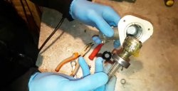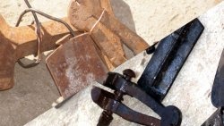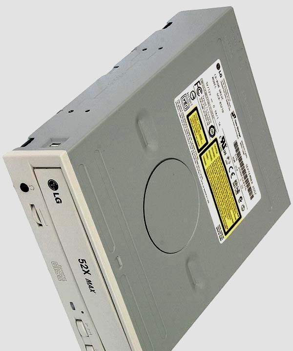
The device must be completely disassembled. For further work you will need:
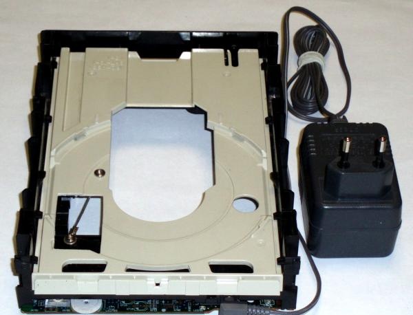
- plastic base, with a motor and gearbox for the tray extension mechanism,
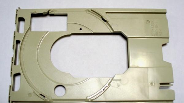
- movable tray,
- front panel board with volume control.
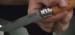
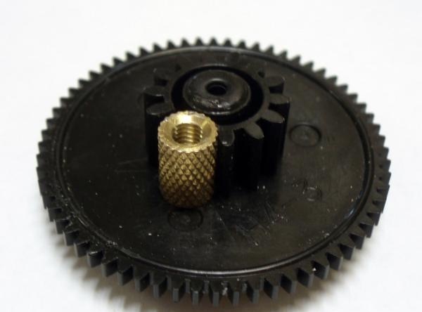
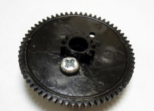
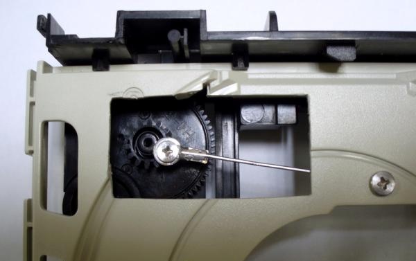
For the reciprocating movement of the tray, we use a crank mechanism. The gearbox gears must be carefully removed. The gear that meshes with the tray's rack requires a little modification. You need to remove two teeth from the ring gears at the top and bottom of the gear using a breadboard knife, freeing up space for installing the crank axis. The axle is a threaded bushing and is attached to the top side of the gear with a short screw.
The modified gear should be tried on to make sure there are no obstacles to free rotation. The screw head, along the trajectory of its movement, can touch the base. This difficulty is eliminated with a breadboard knife; the base plastic is removed at the points of contact with the screw head. Movable tray, modified according to plan. The toothed rack is removed using a hacksaw blade.
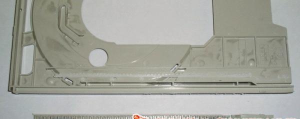
In the place where the crank is located, a hole is made in the tray (in my case, about 20 by 40 mm), in order to simplify assembly and avoid the crank axis touching the bottom surface of the tray.
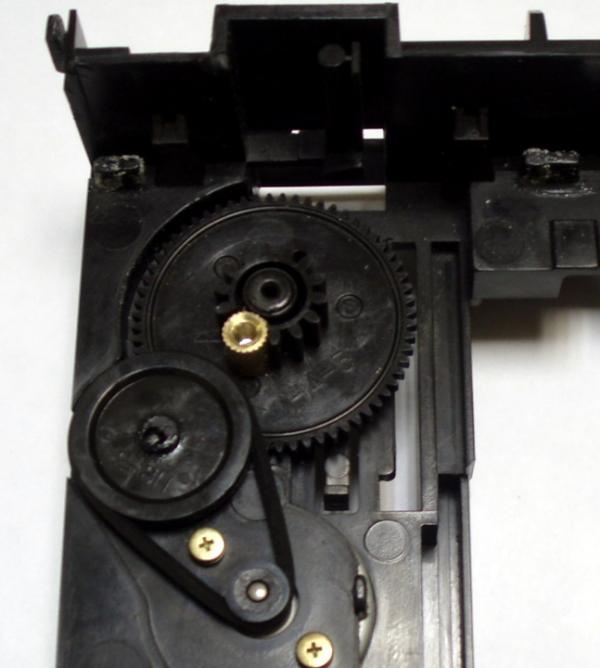
Now you can assemble the gearbox and check the mobility of the parts.
To transmit movement to the tray, you will need to make a connecting rod.
I made a connecting rod from a thick paper clip and two electrical terminals, with a 3mm diameter hole. The workpieces are connected by soldering.
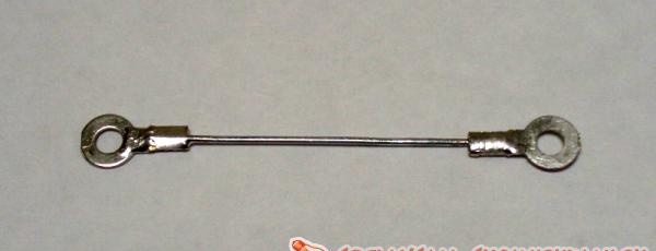
The connecting rod is mounted movably on the tray using an M3 screw and a nut with a lock nut. On the crank axis, with an M3 screw (long enough to rest against the screw securing the threaded bushing, while maintaining the mobility of the connecting rod).
To smoothly change the oscillation frequency of the tray, I made a regulator to control the drive motor.
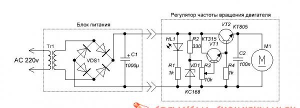
The circuit is a simple stabilizer, the voltage is adjustable from 0 to 6.5 volts.
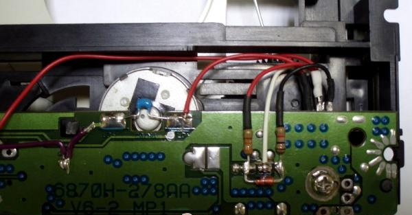
The stabilizer parts are mounted mounted on the front panel board.
All components should be removed from the board except the variable resistor.
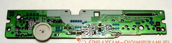
The traces of the printed circuit board through which unwanted connections may form can be severed with a scalpel. Two sections of a variable resistor are connected in parallel. The current flowing through the motor is not large; additional measures to cool the regulator transistors are not required. For clarity, I have depicted a wiring diagram of the regulator with all connections.
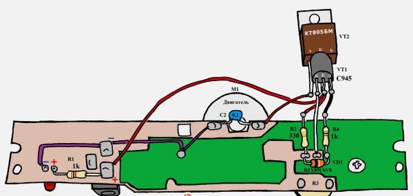
The solder joints at the transistor terminals are insulated with heat shrink tubing. The transistors are attached to the back of the board.
A power supply with a constant voltage of 7.5 to 12 volts can be “borrowed” from a modem, router, wireless access point, etc.
I used the power supply from a Panasonic DECT phone (most of the time it works for its intended purpose).
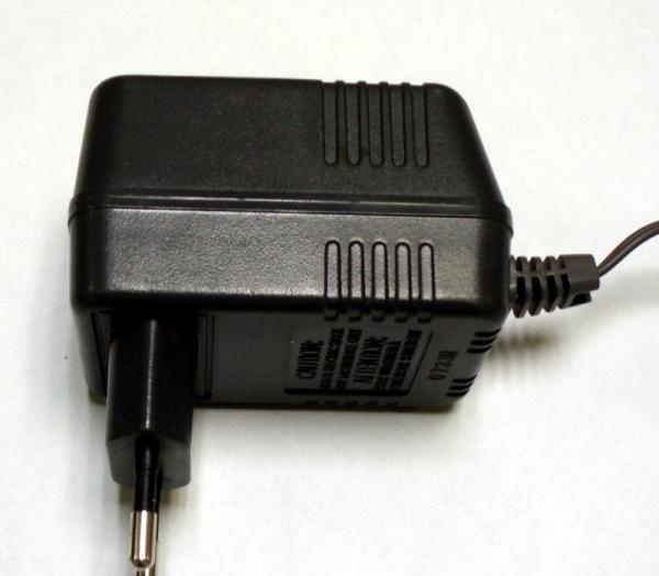
Of course, for the connector on the power supply, you need to select the appropriate connector for installation on the board and connect it correctly.
In general, the shaker turned out to be an unpretentious device and useful in all respects.
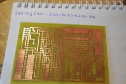
It is convenient to use plastic ice cream tubs as a container for etching boards. The solution volume is usually 100 - 150 ml, the etching time of printed circuit boards is noticeably reduced (even with weak and old solutions). Due to the uniformity of etching and less time the board is in the solution, it is possible to avoid characteristic defects (“under-etching” and “over-etching”).