Every person who assembles electronic circuits needs a universal power source that allows them to vary the output voltage over a wide range, control the current, and, if necessary, turn off the powered device. In stores, such laboratory power supplies are very expensive, but you can assemble one yourself from common radio components.
The presented power supply includes:
- Voltage adjustment up to 24 volts;
- The maximum current supplied to the load is up to 5 amperes;
- Current protection with a choice of several fixed values;
- Active cooling for operation at high currents;
- Dial current and voltage indicators;
Voltage regulator circuit
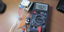
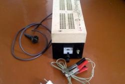
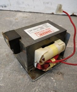
The simplest and most affordable option for a voltage regulator is a circuit on a special microcircuit called a voltage stabilizer. The most suitable option is LM338, it provides a maximum current of 5 A and a minimum of output ripple. LM350 and LM317 are also suitable here, but the maximum current in this case will be 3 A and 1.5 A, respectively.A variable resistor is used to regulate the voltage; its value depends on the maximum voltage required to be obtained at the output. If the maximum output required is 24 volts, a variable resistor with a resistance of 4.3 kOhm is required. In this case, you need to take a standard 4.7 kOhm potentiometer and connect a 47 kOhm constant in parallel with it, the total resistance will be approximately 4.3 kOhm. To power the entire circuit, you need a DC source with a voltage of 24-35 volts, in my case this is a regular transformer with a built-in rectifier. You can also use laptop chargers or other various pulse sources that are suitable for current.
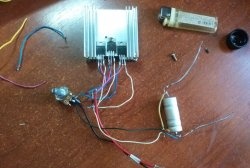
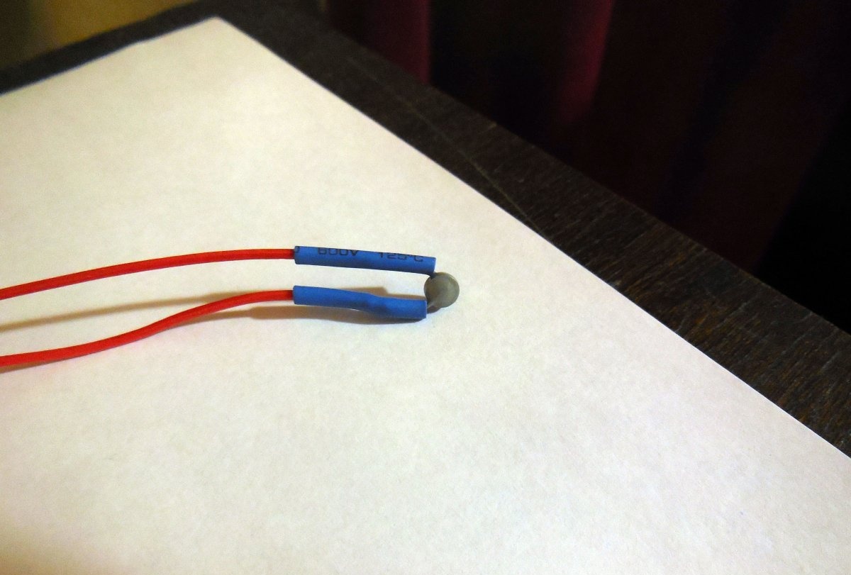
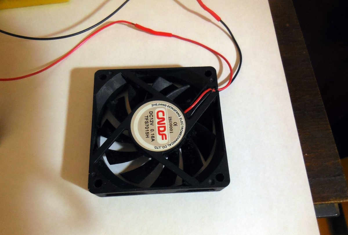
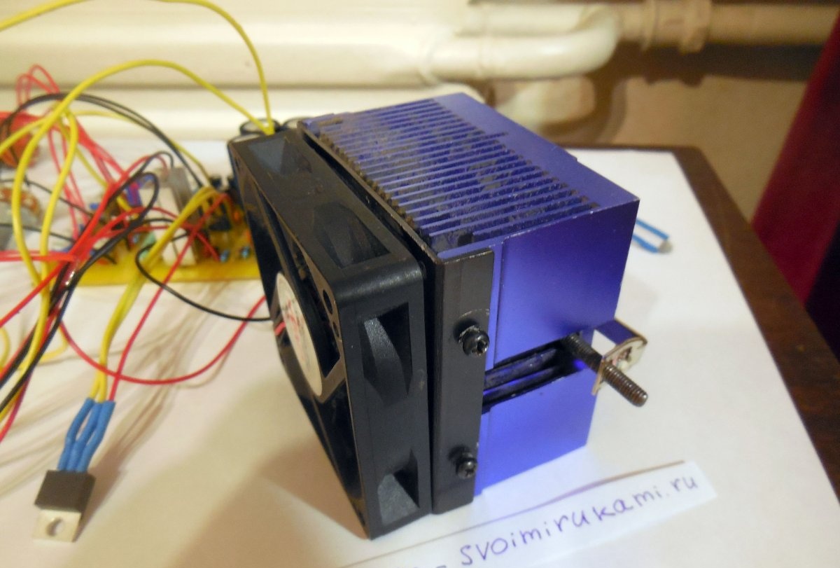
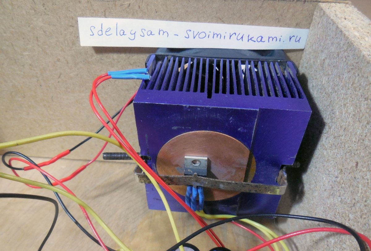
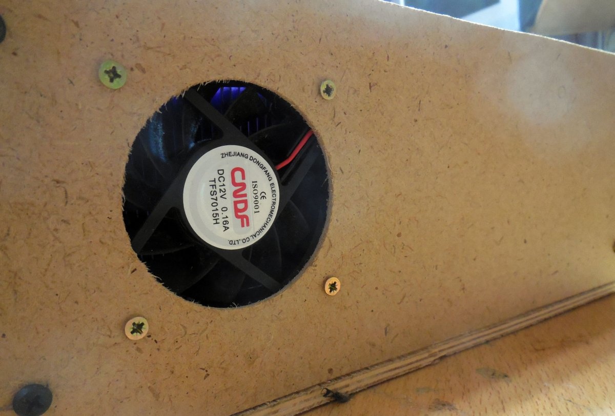
This voltage regulator is linear, which means that the entire difference between the input and output voltage falls on one chip and is dissipated on it in the form of heat. At high currents this is very critical, so the microcircuit must be installed on a large radiator; a radiator from a computer processor, paired with a fan, is best suited for this. To ensure that the fan does not spin all the time in vain, but turns on only when the radiator heats up, it is necessary to assemble a small temperature sensor.
Fan control circuit
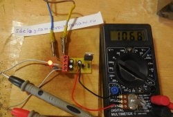
It is based on an NTC thermistor, the resistance of which varies depending on the temperature - as the temperature increases, the resistance decreases significantly, and vice versa. The operational amplifier acts as a comparator, registering changes in the resistance of the thermistor. When the operating threshold is reached, voltage appears at the output of the op-amp, the transistor unlocks and starts the fan, along with which the fan lights up. Light-emitting diode. The trimming resistor is used to adjust the response threshold; its value should be selected based on the resistance of the thermistor at room temperature. Let's say the thermistor has a resistance of 100 kOhm, the trimming resistor in this case should have a nominal value of approximately 150-200 kOhm. The main advantage of this scheme is the presence of hysteresis, i.e. differences between the thresholds for turning the fan on and off. Thanks to hysteresis, the fan does not switch on and off frequently at temperatures close to the threshold. The thermistor is wired directly to the radiator and installed in any convenient place.
Current protection circuit
Perhaps the most important part of the entire power supply is the current protection. It works as follows: the voltage drop across the shunt (0.1 Ohm resistor) is amplified to a level of 7-9 volts and is compared with the reference using a comparator. The reference voltage for comparison is set by four trimming resistors in the range from zero to 12 volts, the input of the operational amplifier is connected to the resistors through a 4-position flip switch. Thus, by changing the position of the biscuit switch, we can choose from 4 preset options for protection currents. For example, you can set the following values: 100 mA, 500 mA, 1.5 A, 3 A. If the current set by the slide switch is exceeded, the protection will work, the voltage will stop flowing to the output and the Light-emitting diode. To reset the protection, just briefly press the button, the output voltage will appear again.The fifth trimming resistor is necessary to set the gain (sensitivity); it must be set so that with a current through the shunt of 1 Ampere, the voltage at the output of the op-amp is approximately 1-2 volts. The hysteresis setting resistor for the protection is responsible for the “clearness” of the circuit’s latching; it needs to be adjusted if the output voltage does not disappear completely. This circuit is good because it has a high response speed, instantly turning on the protection when the current is exceeded.
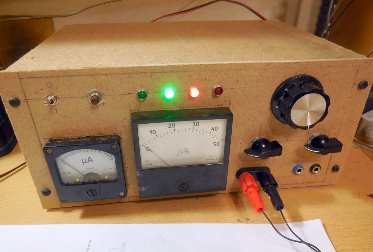
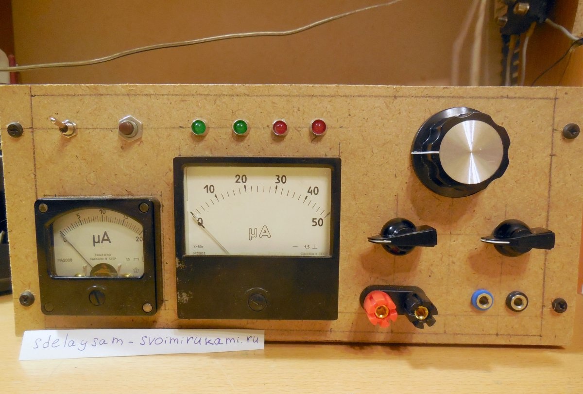
Current and voltage display unit
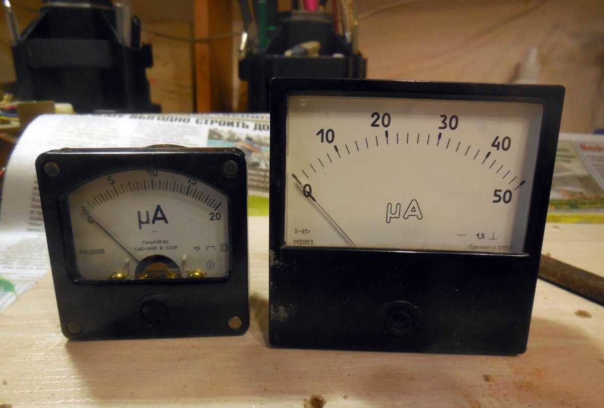
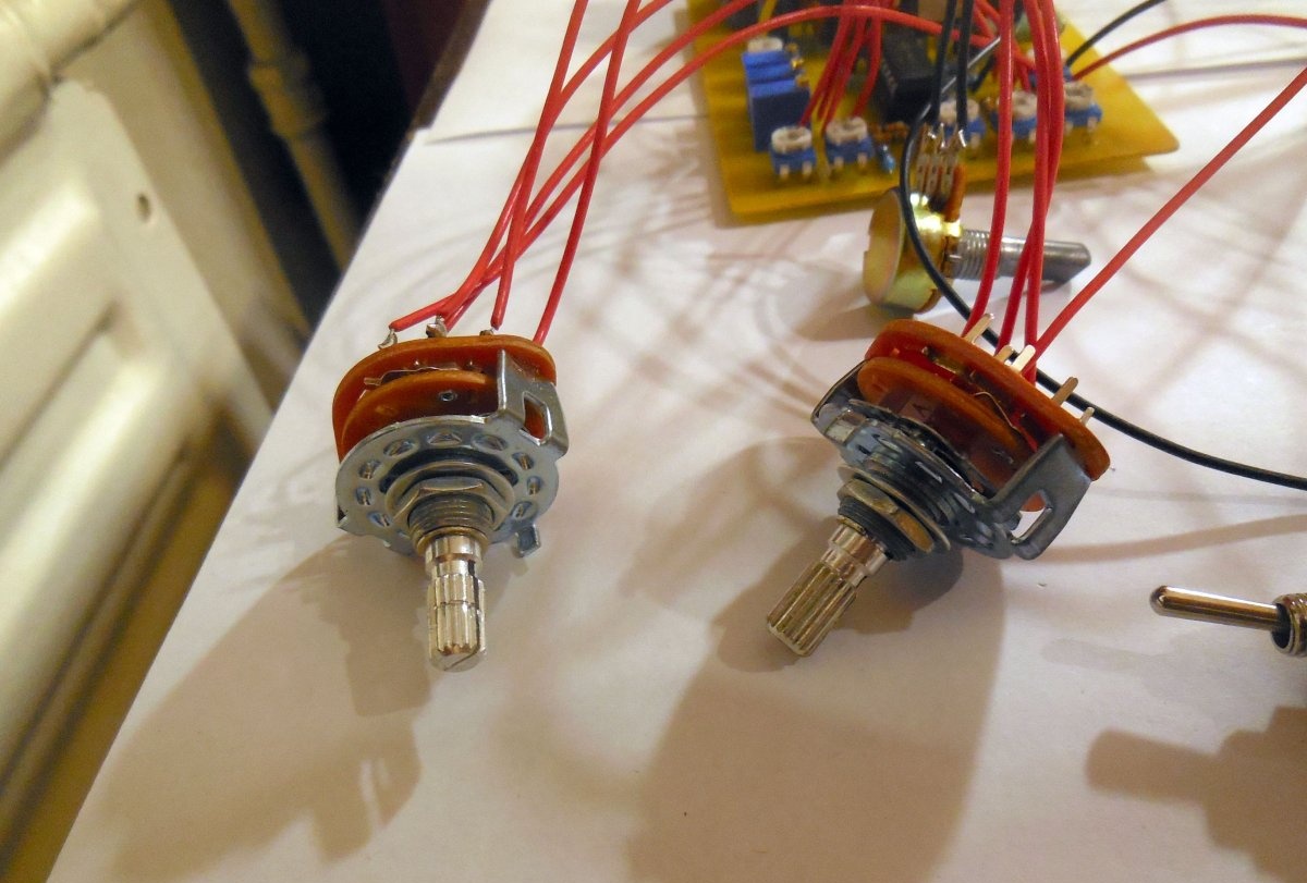
Most laboratory power supplies are equipped with digital voltmeters and ammeters that display values as numbers on a display. This option is compact and provides good accuracy of readings, but is completely inconvenient to read. That is why it was decided to use arrow heads for indication, the readings of which are easy and pleasant to perceive. In the case of a voltmeter, everything is simple - it is connected to the output terminals of the power supply through a trimming resistor with a resistance of approximately 1-2 MOhm. For proper operation of the ammeter, a shunt amplifier is required, the circuit of which is shown below.
A trim resistor is needed to adjust the gain; in most cases, it is enough to leave it in the middle position (approximately 20-25 kOhm). The pointer head is connected via a biscuit switch, with which you can select one of three trimming resistors, with the help of which the maximum deviation current of the ammeter is set. Thus, the ammeter can operate in three ranges - up to 50 mA, up to 500 mA, up to 5A, this ensures maximum accuracy of readings at any load current.
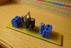
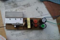
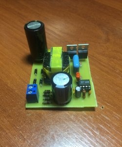
Power supply board assembly
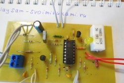
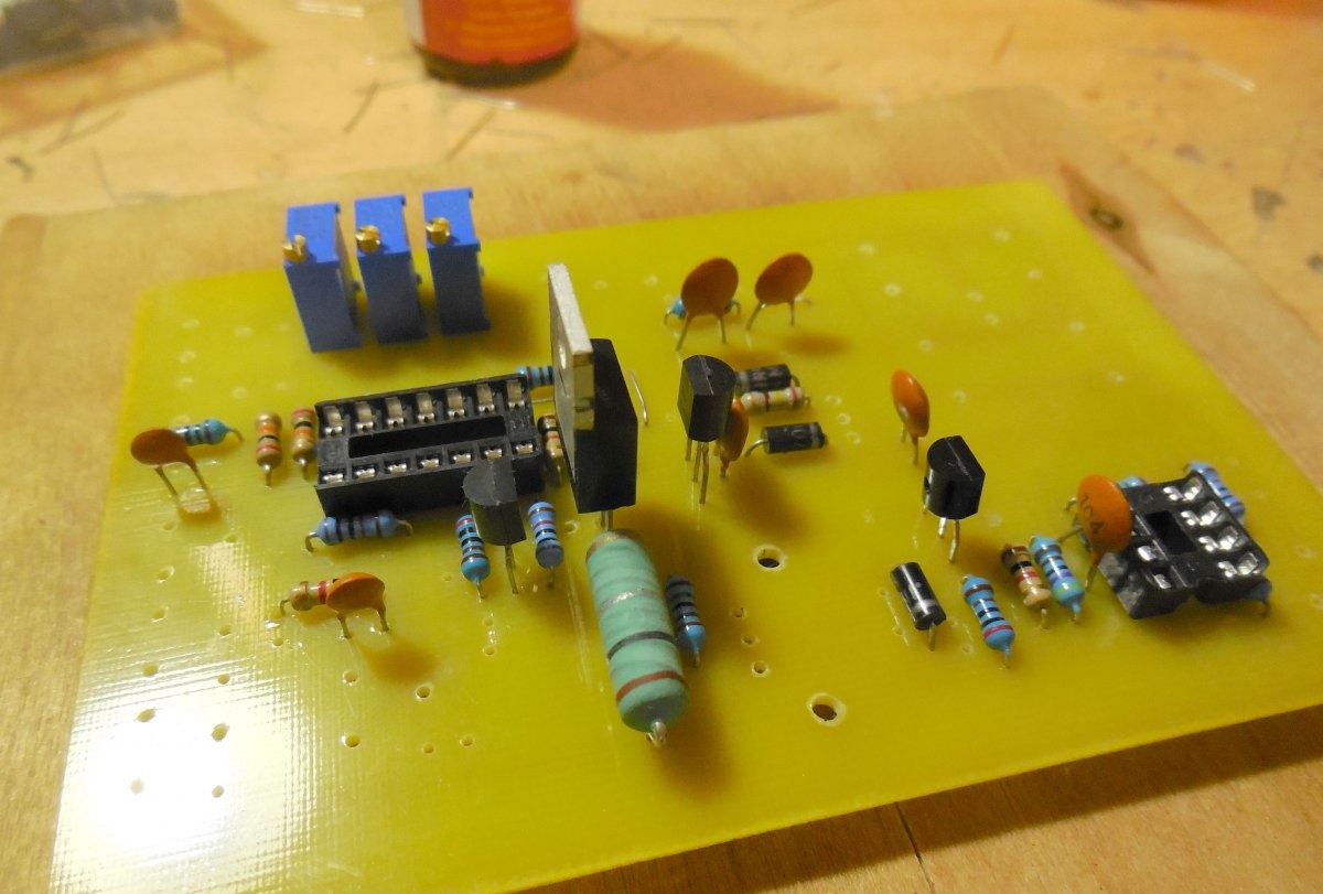
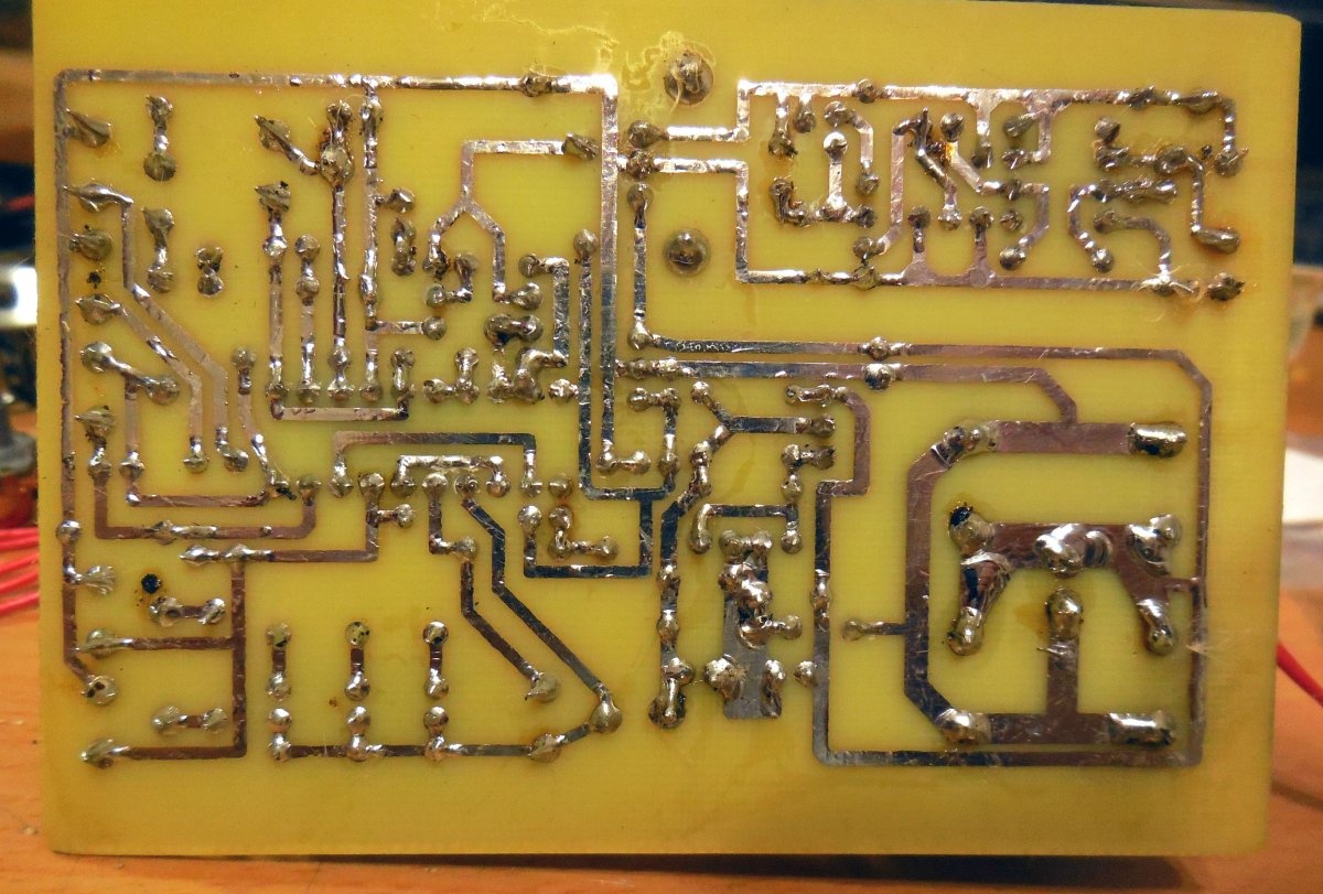
Printed circuit board:Now that all theoretical aspects have been taken into account, we can begin assembling the electronic part of the structure. All elements of the power supply - voltage regulator, radiator temperature sensor, protection unit, shunt amplifier for the ammeter - are assembled on one board, the dimensions of which are 100x70 mm. The board is made using the LUT method; below are several photographs of the manufacturing process.
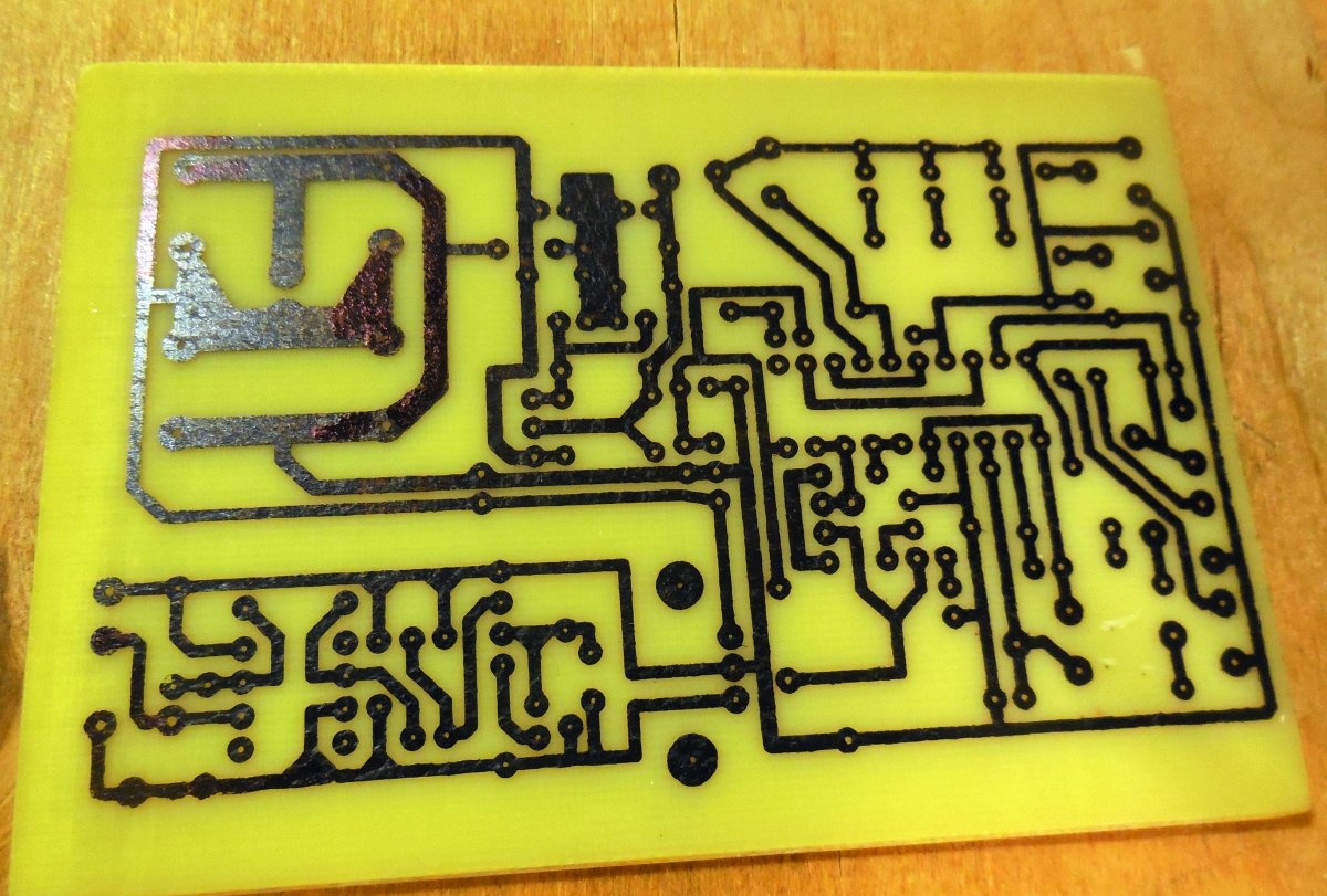
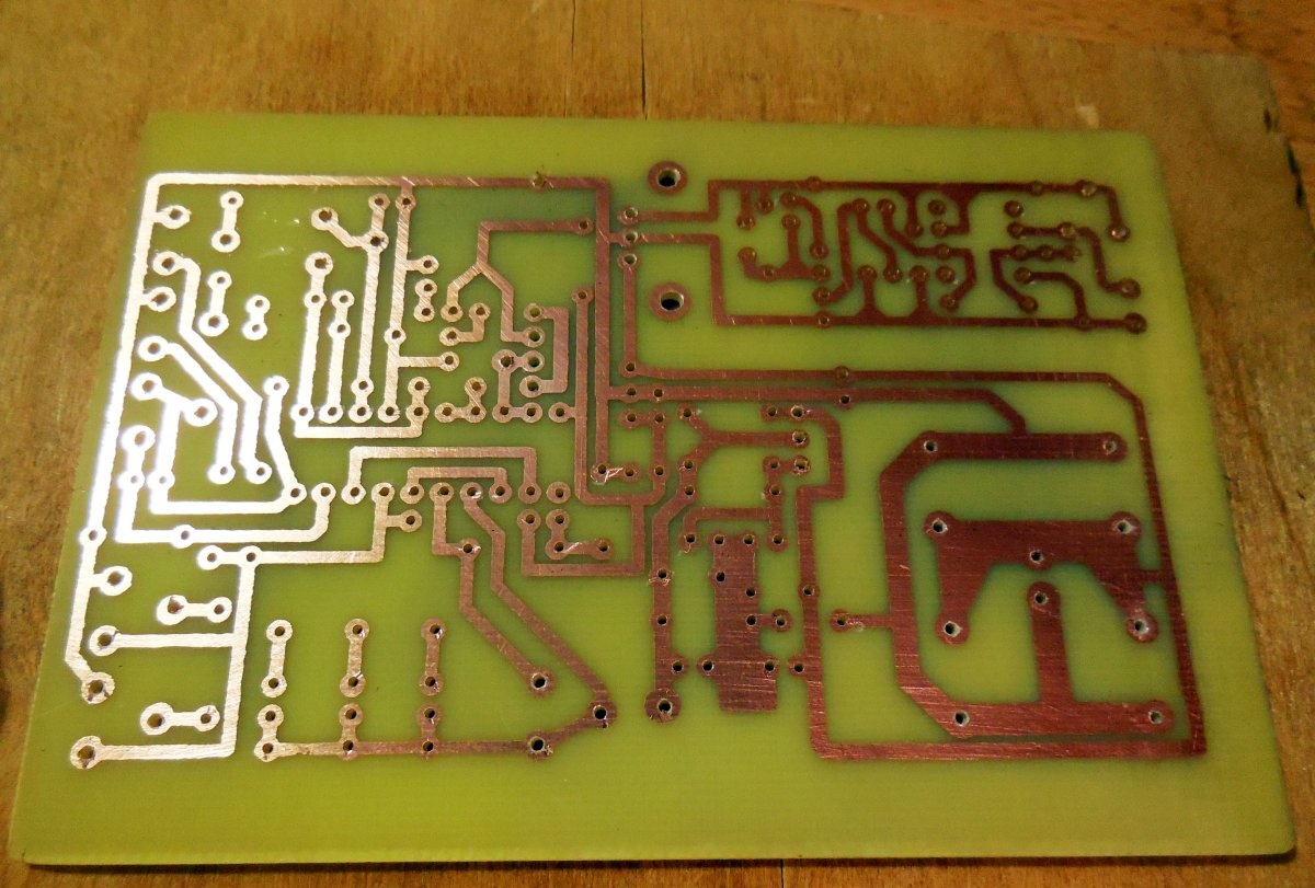
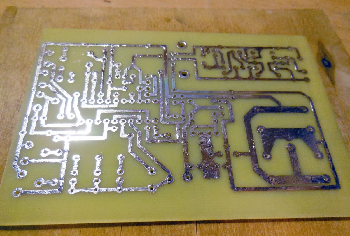
It is advisable to tin the power paths along which the load current flows with a thick layer of solder to reduce resistance. First, small parts are installed on the board.
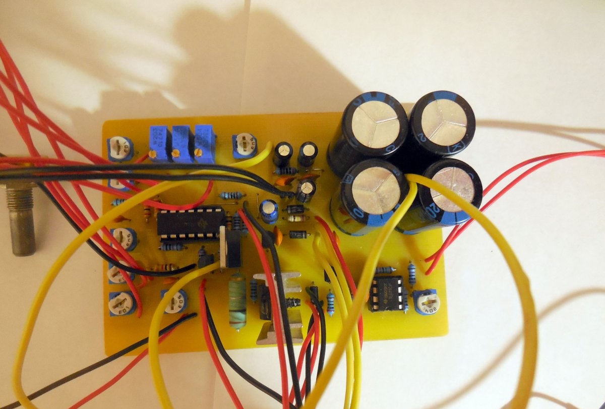
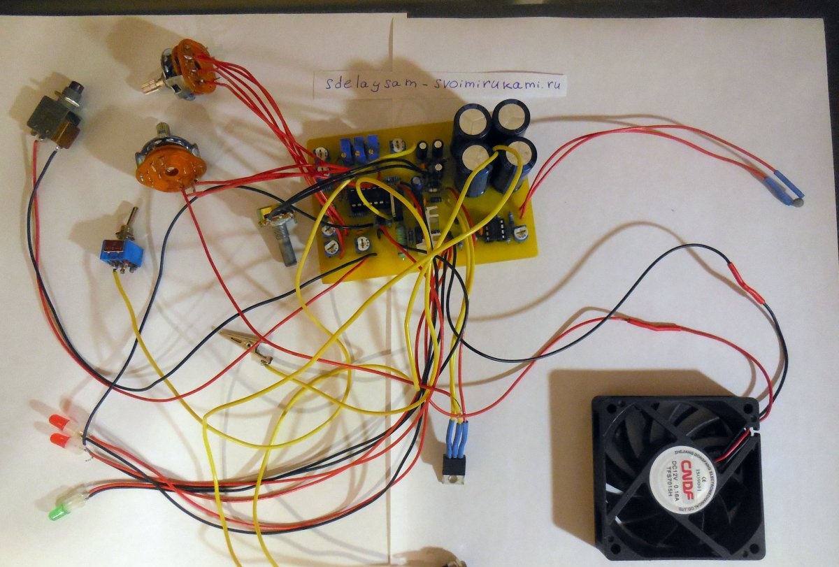
After that all other components. The 78L12 chip, which powers the temperature sensor and cooler, must be installed on a small radiator, the place for which is provided on the printed circuit board. Lastly, wires are soldered onto the board, on which the fan, thermistor, protection reset button, biscuit switches, LEDs, LM338 chip, voltage input and output. It is most convenient to connect the voltage input via a DC connector, but it must be taken into account that it must provide a large current. All power wires must be used with a cross-section appropriate for the current, preferably copper. The plus output from the printed circuit board goes to the output terminals not directly, but through a toggle switch with two groups of contacts. The second group turns on and off Light-emitting diode, indicating whether voltage is supplied to the terminals.
Housing assembly
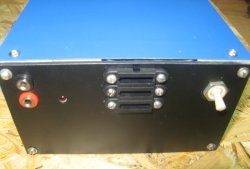
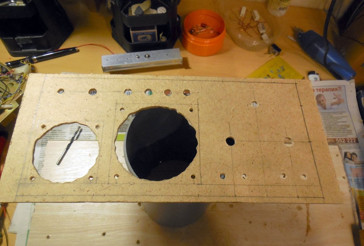
The case can either be found ready-made or assembled yourself. You can make it, for example, from plywood and fiberboard, as I did. First of all, a rectangular front panel is cut out, on which all the controls will be installed.
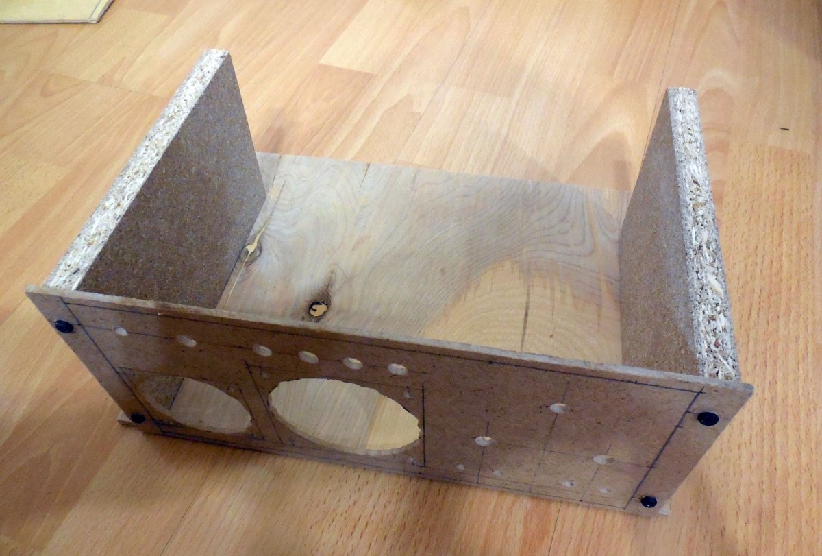
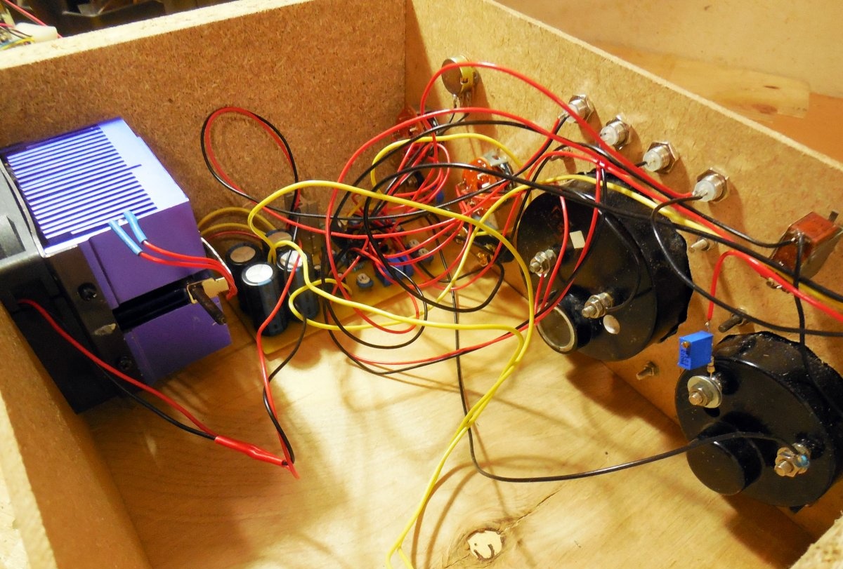
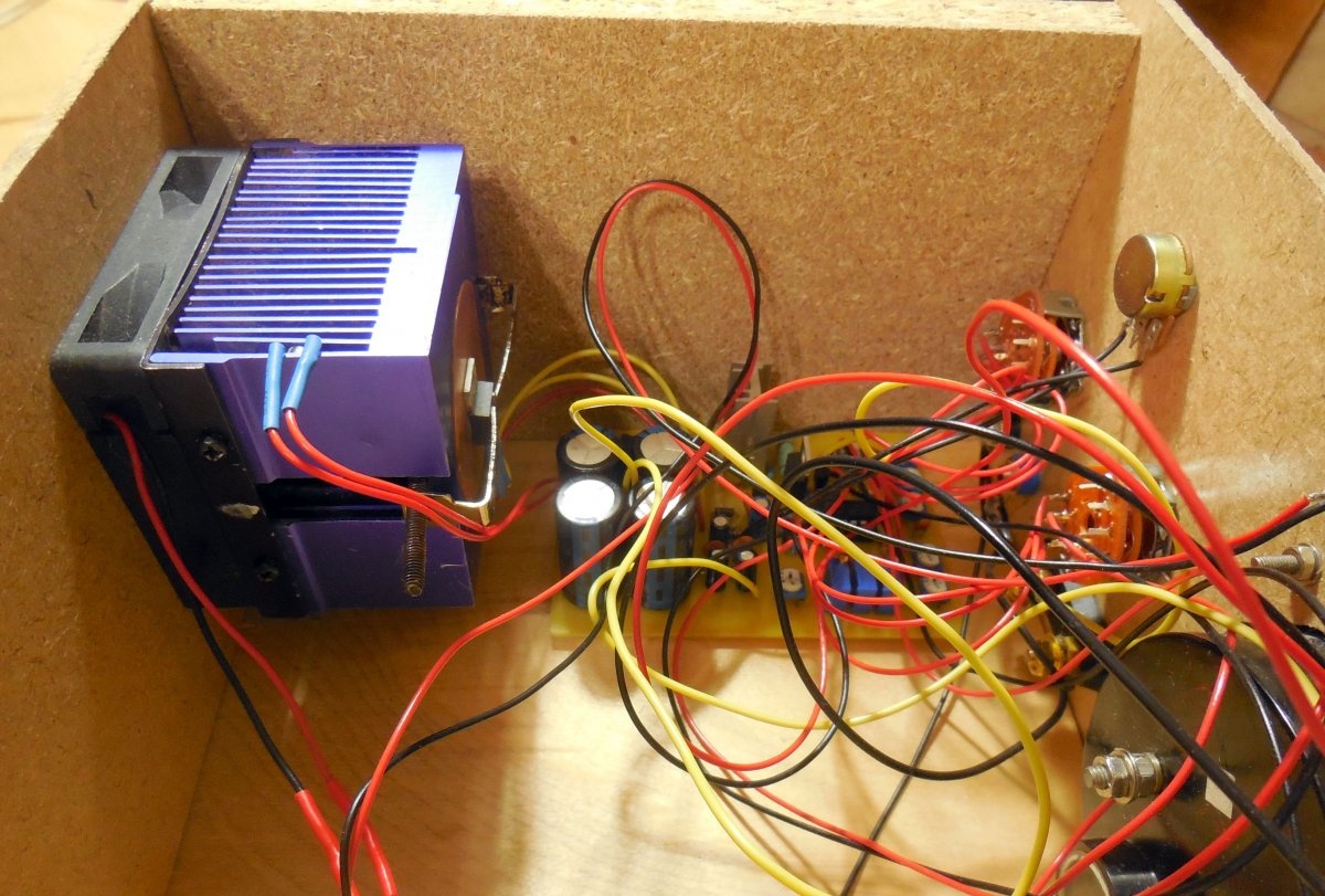
Then the walls and bottom of the box are made, and the structure is fastened together with self-tapping screws. When the frame is ready, you can install all the electronics inside.
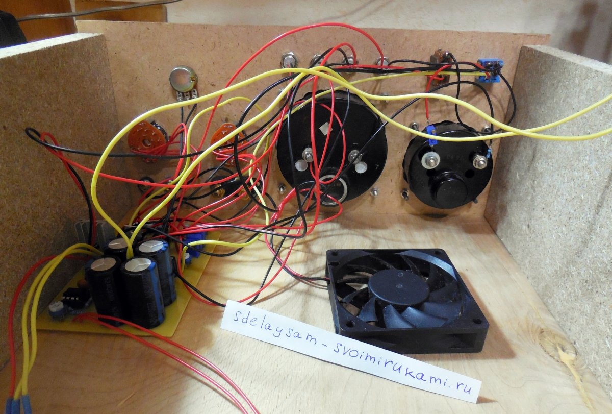
Controls, pointer heads, LEDs are installed in their places in the front panel, the board is placed inside the case, the radiator and fan are mounted on the rear panel. Special holders are used to mount LEDs. It is advisable to duplicate the output terminals, especially since space allows. The dimensions of the case turned out to be 290x200x120 mm; there is still a lot of free space inside the case, and, for example, a transformer to power the entire device can fit there.

Settings
Despite the many trimmer resistors, setting up the power supply is quite simple. First of all, we calibrate the voltmeter by connecting an external one to the output terminals. By rotating the trimming resistor connected in series with the pointer head of the voltmeter, we achieve equality of readings. Then we connect some load with an ammeter to the output and calibrate the shunt amplifier. By rotating each of the three subscript resistors, we achieve coincidence in the readings on each of the three measurement ranges of the ammeter - in my case it is 50 mA, 500 mA and 5A. Next, we set the necessary protection currents using four trimming resistors. This is not difficult to do, given that the standard ammeter is already calibrated and shows the exact current. We gradually increase the voltage (at the same time the current also increases) and see at what current the protection is triggered. Then we rotate each of the resistors, setting the four required protection currents, between which you can switch using a flip switch. Now all that remains is to set the desired response threshold of the radiator temperature sensor - the setup is complete.