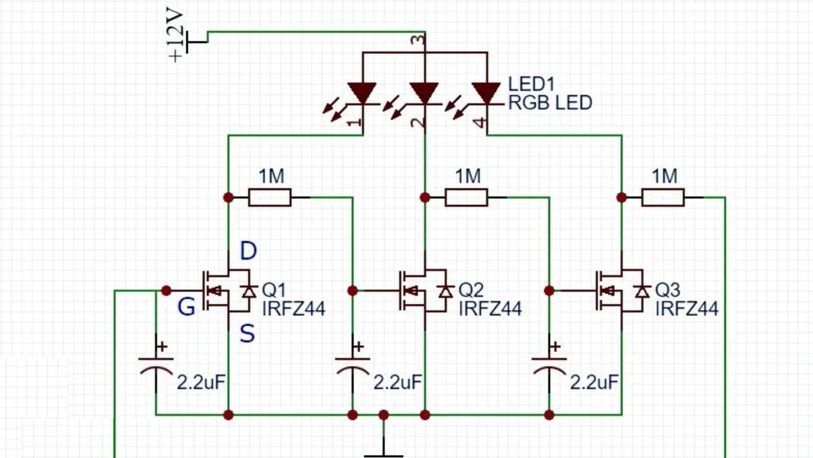
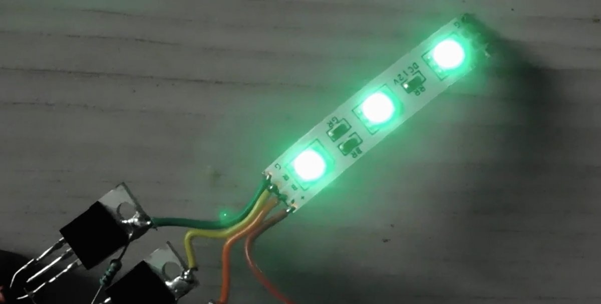
To create the effect of alternating RGB changes LEDs tape, it is proposed to assemble a simple electronic control circuit. The voltage from each of the three outputs of the self-oscillating ring multivibrator is alternately supplied to the input R, G or B of the strip LEDs. At a certain point in time, only red, green or blue lights up. The switching duration is set by the parameters of the time-setting circuit consisting of a resistor and capacitor.
Necessary parts, tools
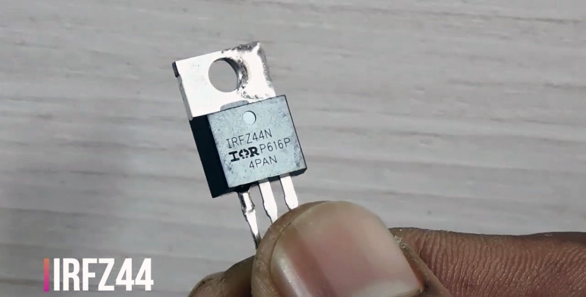
For production you need 3 radio-electronic elements:- Field-effect n-channel MOSFET transistor type IRFZ44. It is used in adjustable current sources, stabilized converters, control systems, monitoring electronic components and units.
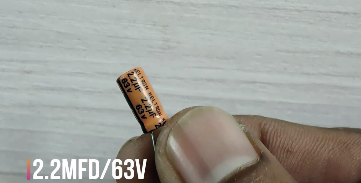
- Aluminum electrolytic capacitor with a capacity of 2.2 microfarads with an operating voltage of at least 25 volts. The nominal parameters are indicated on the housing.
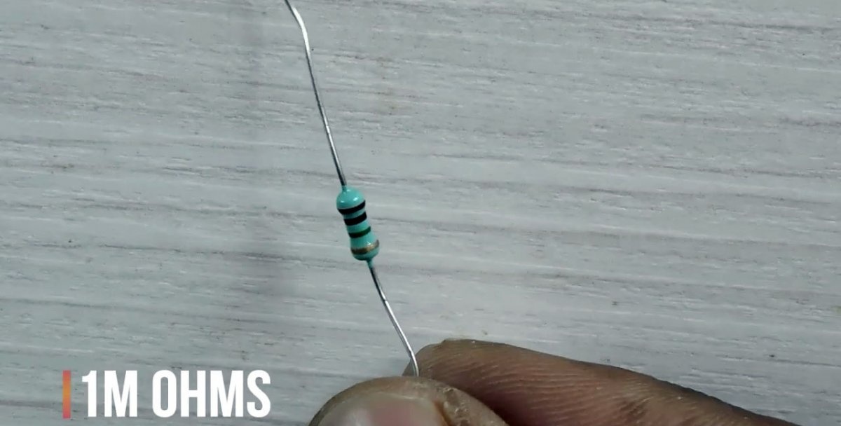
- A fixed resistor with a heat dissipation power of at least 0.125 watts and an active resistance of 1 megohm.
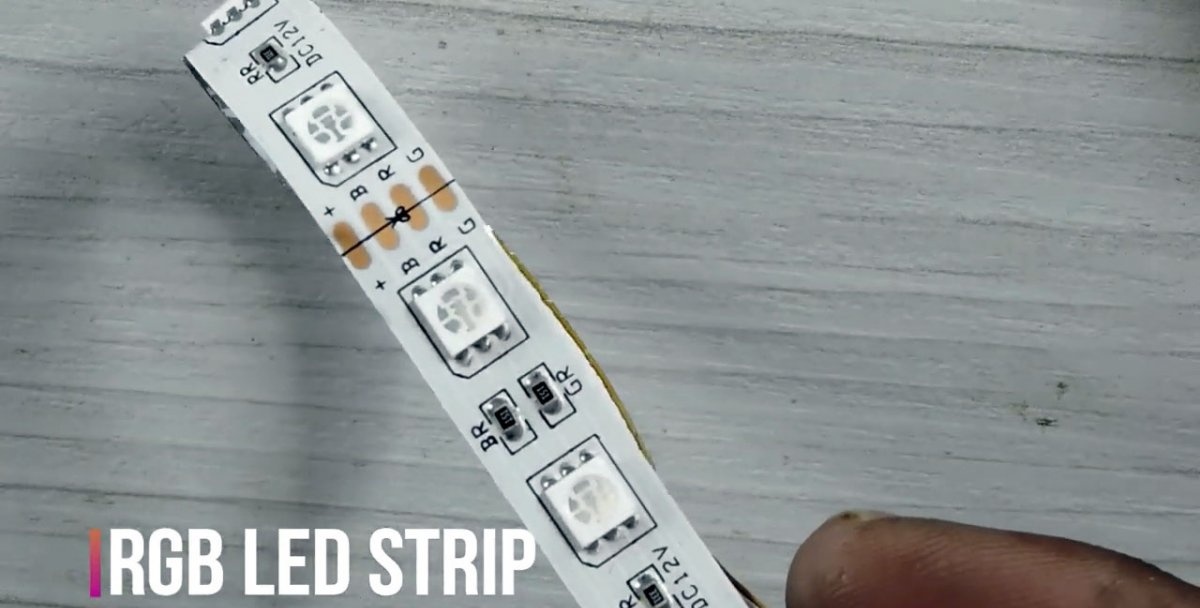
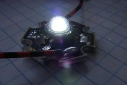
The node is connected to a three-color LED strip of type SMD5050 or similar with a 12-volt power supply. The strip contains modules, each of which contains 3 three-color diodes. The corresponding color and power terminals, connected in parallel, are brought out to the connection points on the canvas. The control signals for each glow are sent to LEDs through a personal current-limiting resistor. Parallel connected modules are placed on a tape up to 5 meters long.
Any soldering iron is suitable for reliable connection of radio components. You can use pliers, wire cutters or a knife to give the leads a convenient shape for work, bend them and cut them to the required length. The unit operates from a constant current source of 12 volts.
Assembling the controller circuit
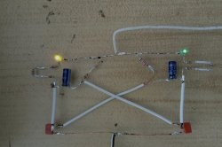
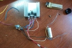
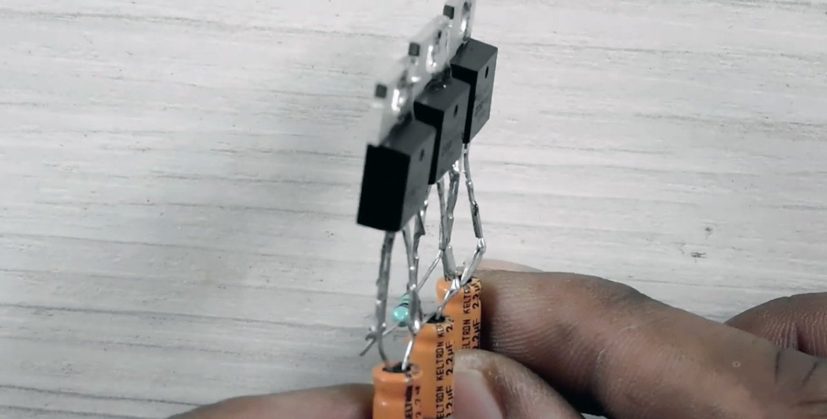
There are few parts, so it is convenient to do the installation using a hinged method, when the elements are soldered directly to each other without intermediate contacts, supports or assembly boards.
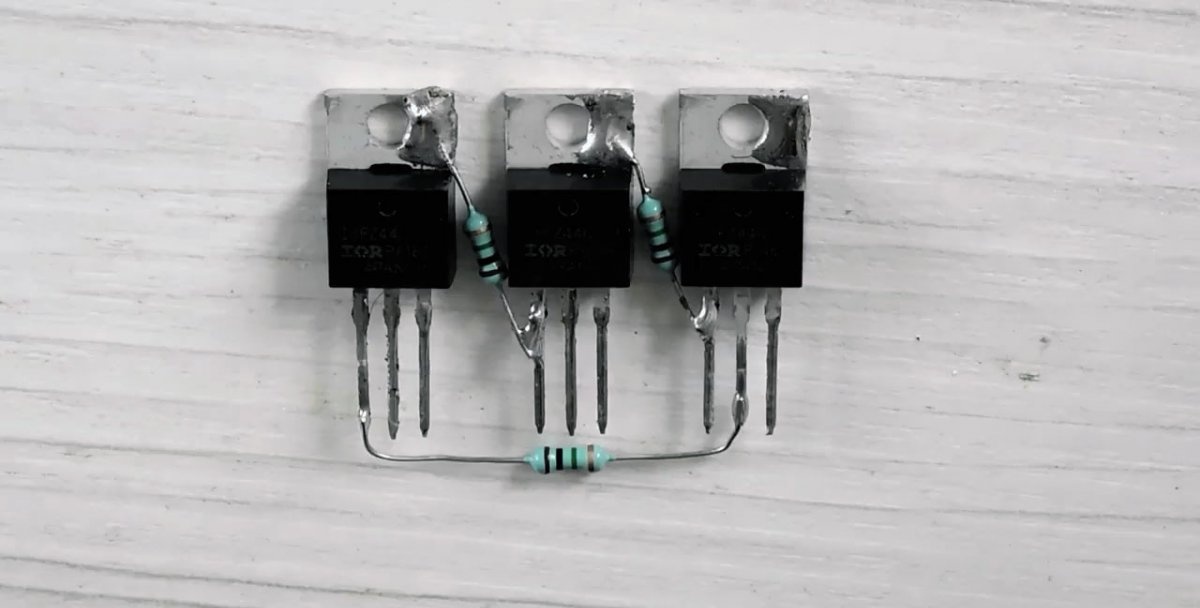
The transistor crystal is placed inside a plastic housing. The centrally located "Drain" is also connected to a large metal heat sink. It is usually used to attach to the wall of an electronic unit. The metal of the radiator is easy to tin, so it is convenient to use it as a contact pad for soldering resistance.
Its second end is connected to the “Shutter” terminal of the next element.
The third transistor is connected in the same way, but its “Drain” is connected through a resistor to the “Gate” electrode of the first stage, forming a ring.
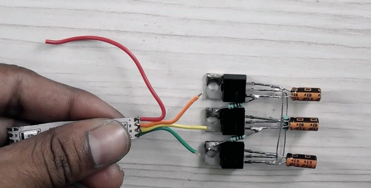
The capacitor is connected between the “Gate” and “Source” electrodes of each transistor. You must first correctly determine the polarity of the component by the markings on the case. Usually the negative electrode is marked, which we solder to the “Source”.
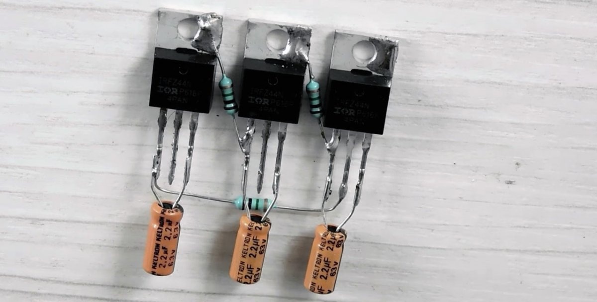
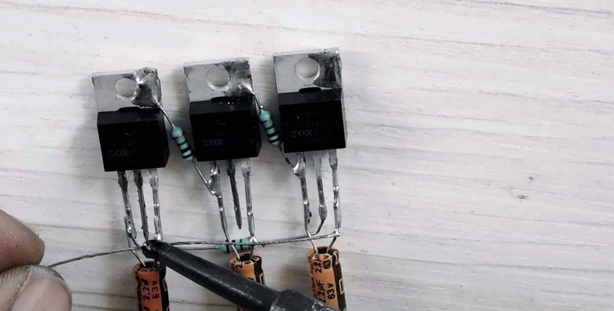
A piece of wire connects the “Source” of all transistors to each other, creating a connection bus for the “minus” terminal of the power supply. The rigid electrodes of transistors are easy to move apart and form into a stable shape to avoid accidental short circuits.
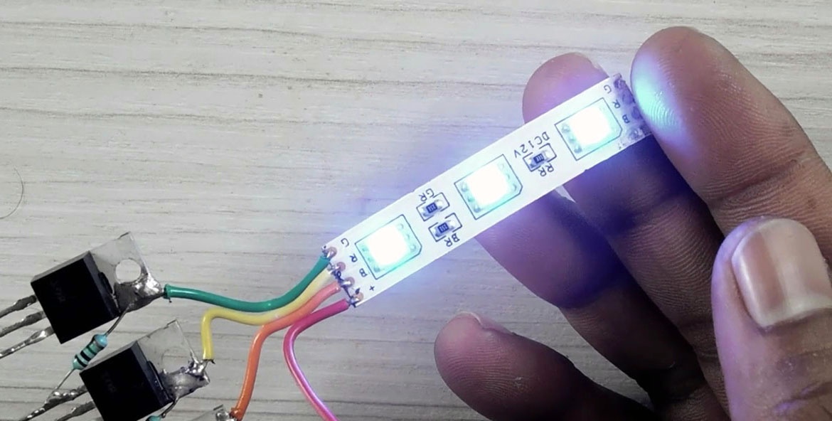
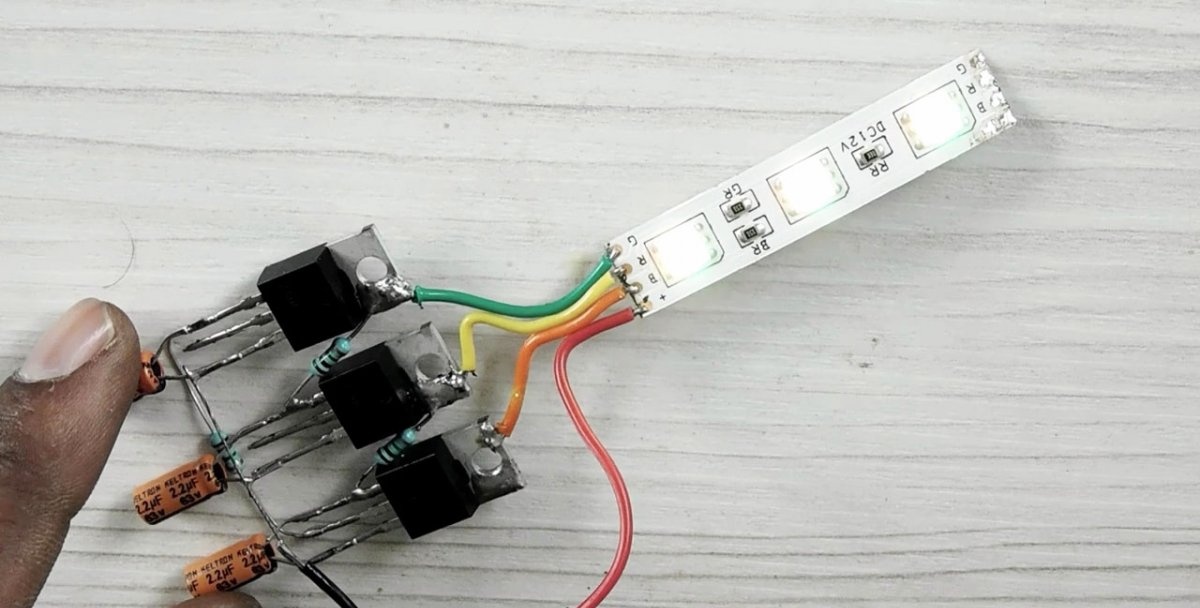
The LED strip shows the switching points “R”, “G” and “B”. Using pieces of insulated wire, each of them is connected to the “Drain” of one of the transistors.
The “plus” of the current source is connected to the “+” terminal of the tape, the “minus” is soldered to the “Source” bus of the transistors.
Assembled from serviceable parts and with complete installation compliance with the circuit diagram, the controller begins to work after switching on without the need for preliminary configuration or selection of element parameters. The switching frequency will decrease as the capacitance value increases and vice versa.
Advice
Soldering will be easier and faster if the leads of the radio components are pre-tinned. When working with a soldering iron, you need to ensure that the room is properly ventilated and be careful not to get a thermal burn or electrical shock.