Do it yourself
Life hacks, master classes, useful tips, recipes.
home » Electronics » DIY electronics » Electronic pass-through switch with any number of switches

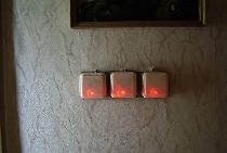
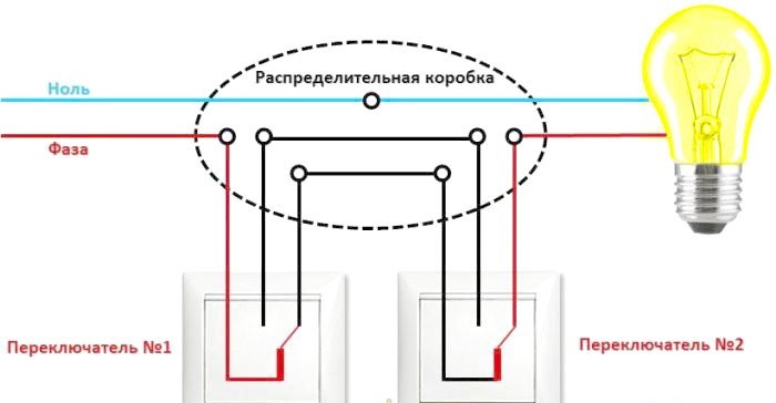
Walk-through switches are usually used in long corridors or over long distances when you need to turn lights or electrical appliances on or off in one place and turn them on or off in another. In this case, you have to pull 3-wire or more cables.

Below is a diagram of a standard pass-through switch:

Electronic pass-through switch with any number of switches

The proposed electronic switch is free from these shortcomings; it is installed in a junction box and buttons (switches) are connected from it in parallel with signal wires, which can independently turn on and off lighting or other devices.

Buttons from the bell or any other buttons without latching are used as switches (press and release - turn on the light, press and release again - turn off the light), there are also switches without latching on sale.

Will need

For production you need:

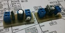
  • Terminal block into the board with a pitch of 5 mm. 3 pcs. (you don’t have to install it, just solder the wires)
  • Resistor 1 K 1206 - 2 pcs.
  • Resistor 100 K 1206 - 6 pcs.
  • Resistor 470 K 1206 - 1 pc.
  • Resistor 10 K 1206 - 1 pc.
  • Capacitor 0.01 uF 1206 - 1 pc.
  • Capacitor 0.1 uF 1206 - 2 pcs.
  • Capacitor 10 uF 1206 - 1 pc.
  • Diode 4007 (any 600-800 V of suitable size) 1 pc.
  • Zener diode 12 V BZV55-C12 (can be 2 pcs. for 5.6 V) 1 pc.
  • Diode bridge DF10S (any suitable size for 1 A 600-1000 V) 1 pc.
  • Transistor IRF840 - 1 pc.
  • Chip ICM7555 (analogous to ALD555, LMC555, TS555, TLC555) - 1 pc.

All components are SMD because the circuit board is made for them.

Scheme

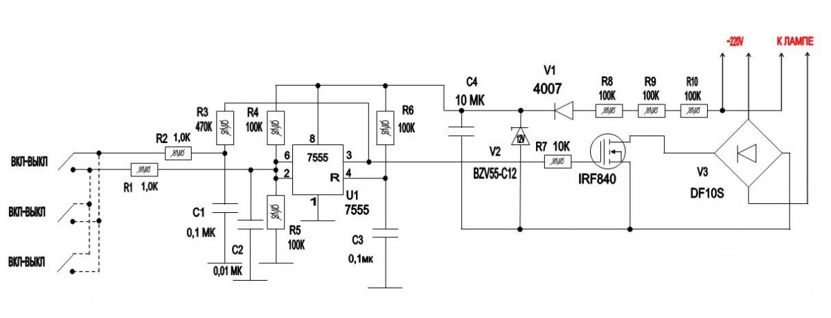
Here is the actual diagram of the device:

Description

a trigger is created on the microcircuit, R1, R2 can be set to 470 Ohm-1.5 K; they are needed to improve noise immunity and partly safety (the design has a galvanic connection to the network).

Circuit R6, C3 is needed so that the trigger is always in the off state when the power is turned on.

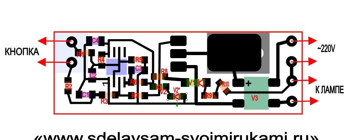
Capacitor C4 is a power filter, zener diode V2 limits the power supply to 12V / there is space on the board to install 2 5.6V zener diodes in series and when using one for 12 V, you need to put a jumper in place of the second one, it is designated V2* on the board.

Resistor R7 can be set with a nominal value of 470 Ohm -20 K; it is needed for stable opening of the transistor and suppressing its self-excitation at the moment of opening/closing.

R8-R10 suppress the mains voltage (why are there 3 of them in series? Because 1 resistor in the 1206 case is designed for a voltage of no more than 200V and for safety and reliability 3 of them are installed)

Buttons or switches without latching receive a voltage of approximately 12 V and you can use any of the lowest current ones, but the circuit is connected to the network, be careful when checking!

Board assembly:

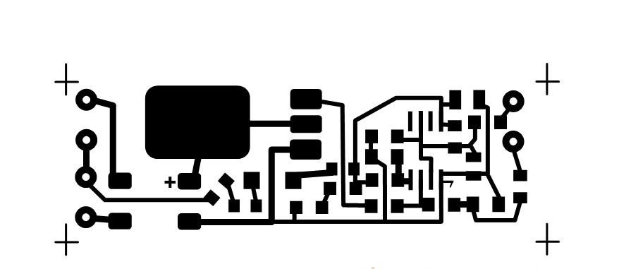
We cut out a board measuring 20x60 mm from one-sided foil fiberglass, clean it with fine sandpaper, and degrease it.We print the board on a laser printer without saving ink on glossy paper from a magazine.

You can download the PCB files here:

fajly.zip [113.48 Kb] (downloads: 457)

Using the LUT method, we apply a design and etch it in ferric chloride. We wash off the toner with acetone and clean it with fine sandpaper. We service the paths and wash off any remaining flux. We solder all the components on the track side.

Wash off the flux! it is very important! The microcircuit is quite high-resistance and if the flux is active it may not work!

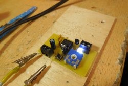
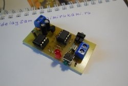
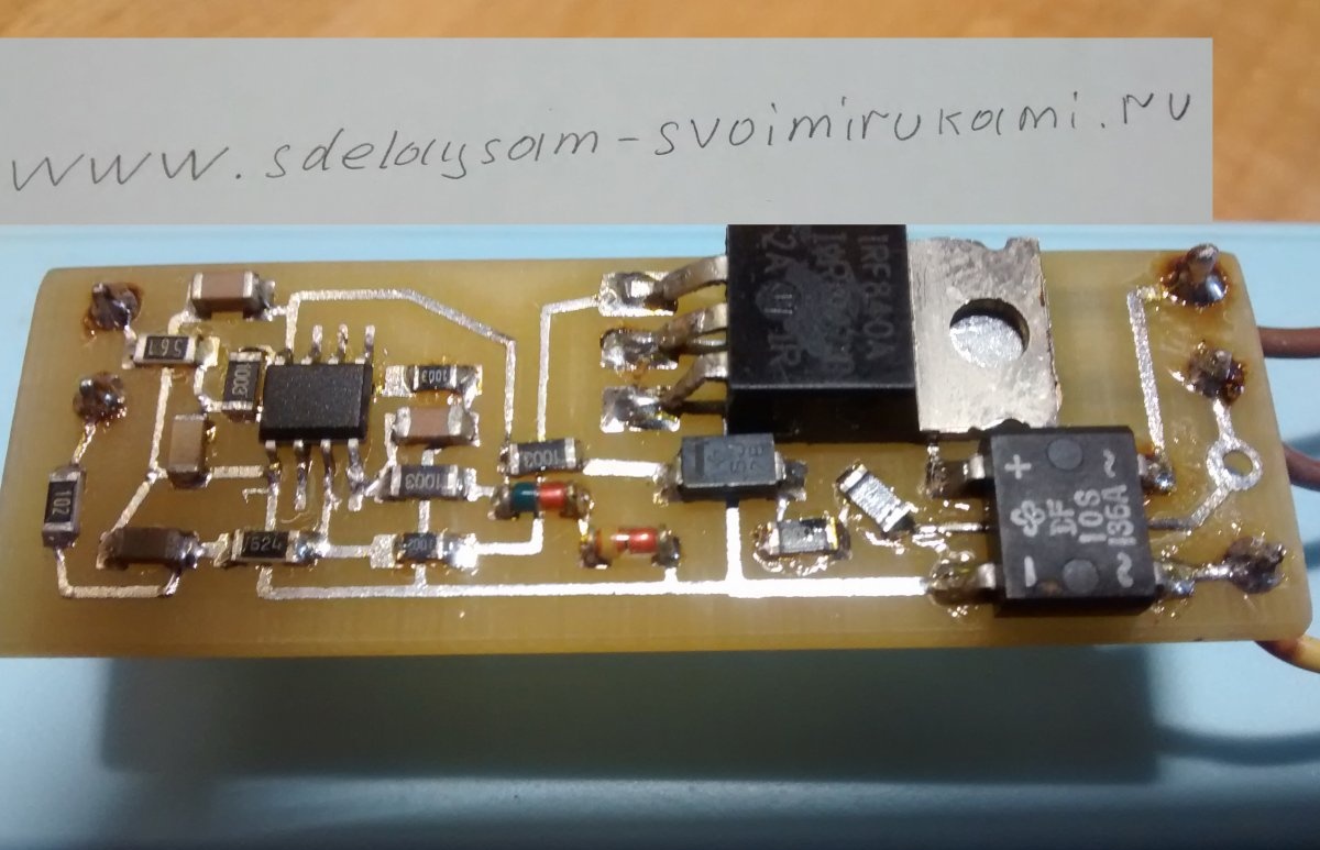
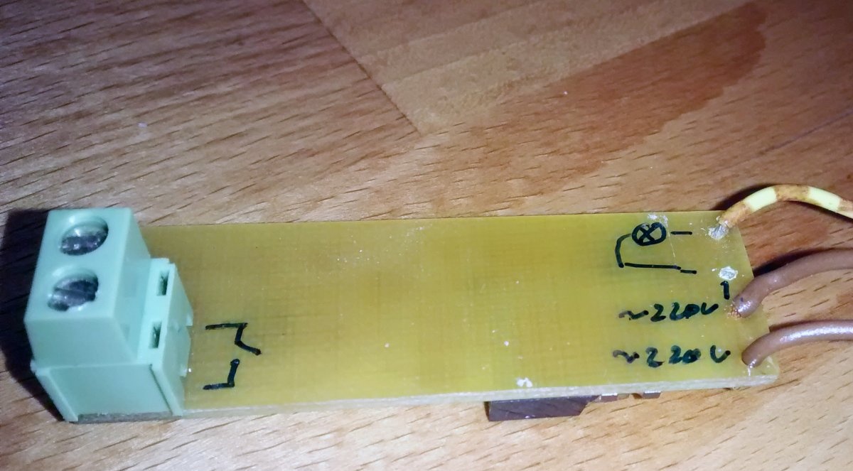
It should look something like this:

Be careful - the design is connected to a 220 V network! Take precautions!

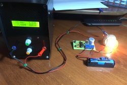
Checking the installation!

We connect the light bulb, button, power cord. We plug it into a 220 V network. Be careful - the design is connected to a 220 V network! Take precautions!

We check the functionality. If everything works fine, take a heat-shrink tube of a suitable diameter and pack the board there for safety.

Characteristics:

Maximum load -150 W (limited by the diode bridge and transistor; when replacing them with more powerful ones, the load can be increased).

Supply voltage -180-250 V.

Power consumption when turned off is 0.1 W.

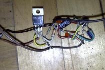
You don’t have to make a board at all if you take a breadboard and solder regular DIP elements with pins on it, connecting them with a wire.

It will just be a little bigger. If you have any questions, write and I will answer.

come back
Comment
  • bowtiesmilelaughingblushsmileyrelaxed relaxedsmirk
    heart_eyeskissing_heartkissing_closed_eyesflushedrelievedsatisfiedgrin
    winkstuck_out_tongue_winking_eyestuck_out_tongue_closed_eyesgrinningkissingstuck_out_tonguesleeping
    worriedfrowninganguishedopen_mouthgrimacingconfusedhushed
    expressionlessunamusedsweat_smilesweatdisappointed_relievedwearypassive
    disappointedconfoundedfearfulcold_sweatperseverecrysob
    joyastonishedscreamtired_faceangryragetriumph
    sleepyyummasksunglassesdizzy_faceimpsmiling_imp
    neutral_faceno_mouthinnocent
5+two=
Comments (20)
  1. Gregory
    #1 Gregory Guests 25 June 2019 19:09
    3
    WHY FENCE SUCH A GARDEN JUST A PASS-THROUGH SWITCH
    1. ozi
      #2 ozi Guests 3 July 2019 18:55
      1
      Passers and impulsers have their pros and cons.
      The bushings are cheap and easy to install linearly. If the load configuration with star-tree “buttons”, an impulse generator is preferable, although more expensive.
  2. Andrey
    #3 Andrey Guests 25 June 2019 21:32
    0
    Pulse relay on DIN rail. No, we haven't heard...
    1. Guest
      #4 Guest Guests 26 June 2019 19:24
      0
      The size doesn’t matter everywhere, you can just install it if the shield is ok, it won’t fit into the terminal box, the pulse relay clicks quite loudly... The price also matters - here the parts cost 150 rubles and the relay costs 1500 rubles..
    2. ozi
      #5 ozi Guests 3 July 2019 18:52
      1
      That's right. Not a passable one.
  3. Guest Yuri
    #6 Guest Yuri Guests 26 June 2019 21:48
    6
    The diagram of a standard pass-through switch drawn above is incorrect. If switch No. 2 is placed in the left position, then switch No. 1 will not work. In the standard circuit, the moving contacts are connected: one to the phase, the second to the lamp, fixed contacts between No. 1 and No. 2 in any order. Well, if there is a mistake in such elementary things, then about the electronics... Well, I’d better keep silent.
    1. Guest
      #7 Guest Guests 27 June 2019 20:32
      2
      Yes, I really didn’t notice the error, but the board circuit is working and you can see in the video that it’s been working for a couple of years already.
  4. Guest Samodelkin
    #8 Guest Samodelkin Guests June 27, 2019 06:28
    1
    There are even more wires
    1. Guest
      #9 Guest Guests 27 June 2019 20:35
      2
      board in the box, and 2 wires to the buttons. Where is there more?
  5. Sergey K
    #10 Sergey K Visitors June 27, 2019 11:34
    1
    The circuit of pass-through switches has a main disadvantage - additional wires in the circuit. This solution is not new; I saw similar circuits in magazines of the 60s, using a different element base. Of course, I would like to see how the author fits the board into the box, but that’s not the point, you can place the circuit in the lamp itself. But the bundle of wires from the box or lamp will not go anywhere!
    There is a second disadvantage to pass-through switches - if the lights are turned off, determining whether the load is on or not is quite problematic

    Today there is a more elegant solution - wireless relays. On Banguda I once bought a 4-channel with two remote controls for only 5-something bucks. Place the remote controls into the switch housing, and the board with relays into the lamp housing. That's all!
    1. Guest
      #11 Guest Guests 27 June 2019 20:39
      2
      Great topic for an article - write and make money! /yes, batteries are needed for the remote controls, and the relay does not fit into every lamp/
      1. ozi
        #12 ozi Guests 3 July 2019 18:58
        1
        Let there be a room with a lamp and a bunch of doors around the perimeter. How will people entering and leaving this room with the remote control/remotes use it and what words will they use to remember the developer.
    2. Guest Yuri
      #13 Guest Yuri Guests July 1, 2019 08:24
      0
      If the light turns off, it is quite easy to determine whether the load is on or not. It is enough to connect the fixed contacts so that if the keys are in the same position, the light will be turned off.
  6. Guest Alexander
    #14 Guest Alexander Guests 2 July 2019 18:37
    0
    too complicated, and not for 150r
  7. Guest Alexander
    #15 Guest Alexander Guests 7 August 2019 16:46
    2
    why IRF840 and not say BT137?
    1. Guest EVA
      #16 Guest EVA Guests 17 August 2019 10:56
      1
      BT137 has a high opening current, you will have to reduce R8-R10 and increase their power, everything will get very hot or use a different method of powering the circuit.
      1. Guest Nikolay
        #17 Guest Nikolay Guests 20 September 2019 12:33
        2
        The solid-state relay "CRIDOM" CX380D5 will serve very well as a power switch in this homemade product. Connected: we replace the field switch with a low-power bipolar structure npn, and instead of the bridge we connect the SSR input. Load current is possible up to 5A. Control voltage 3-15V. The dimensions of the relay fit into a matchbox
    2. Guest Nikolay
      #18 Guest Nikolay Guests 9 September 2019 11:46
      0
      Better than VTA16 with an insulated housing. But to do this, you need to replace the field switch with a bipolar 13001, for example, and you need to introduce another low-power diode assembly (KTs407 or another, for example from a failed LED light bulb) into the triac control electrode circuit.
  8. Guest Nikolay
    #19 Guest Nikolay Guests 7 September 2019 21:23
    1
    Hello! In the diagram there is no power supply to the entire left side via the common wire. Although the board is made correctly.
  9. Guest Victor
    #20 Guest Victor Guests 4 April 2020 21:31
    1
    Hello, I assembled this circuit using only output components. R8, R9, R10 set half-watt at 100 kOhm. I turn it on - it doesn’t work, I measure the alternating voltage at the anode V1, and it gives out one and a half to two volts. What's the problem? Please help me with ideas...

Light Crispy French Fries

Pastry cones for baking | Do it yourself

Why is a resistor connected parallel to the LED in circuits?

How to make sheet plastic from PET bottles

«Do it yourself - with your own hands» - a site of interesting homemade products made from scrap materials and items at home. Step-by-step master classes with photos and descriptions, technologies, life hacks - everything a real master or just a craftsman needs for needlework. Crafts of any complexity, a large selection of directions and ideas for creativity.

We recommend reading

Washing machine error codes