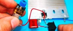
The control device is designed to work with any low-power DC motor. The engine power is limited only by the characteristics of the transistors used in the circuit. The circuit can be powered from a AA battery or another DC source.
The circuit contains two closing buttons that turn on the engine and select the direction of rotation of the rotor. As an option, an LED indicator can be added to the circuit to indicate whether the motor is on and the direction of rotation.
The device is assembled using available components and does not require configuration.
Schematic diagram of the device
The schematic diagram is shown in the figure. The device is based on a pair of identical transistor switches controlled by buttons.
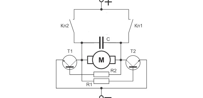
The transistors are connected in series with a DC electric motor “M”, which serves as a collector load for them. When the “Cl1” button plus the power source is activated, the collector of the transistor “T1” is supplied through the electric motor “M”, and to its base through the resistor “R2”.“T1” opens, a current begins to flow through the winding of the motor “M”, under the influence of which the rotor rotates. Additionally included Light-emitting diode “Vd1”, the forward current of which is set by resistor “R3”.
When the “Cl2” button is triggered, the opposite arm of the circuit on the transistor “T2” and the indicator LED “Vd2” functions in a similar way. In this case, the current through the electric motor “M” passes in the opposite direction and the rotor rotates in the other direction.
Motor “M” with its finite resistance for direct current additionally protects transistors “T1”, “T2” from overload. Capacitor “C” ensures a “soft” start of the engine when voltage is supplied to it from the source.
Required radio components
The scheme includes:- electric motor;
- pair of transistors BC547 - http://alii.pub/5l6vyg
- 100 nF capacitor - http://alii.pub/5n14g8
- three resistors 220 Ohm, 0.25 W - http://alii.pub/5h6ouv
- two buttons for closing without fixing - http://alii.pub/5nnu8o
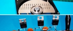
Circuit assembly
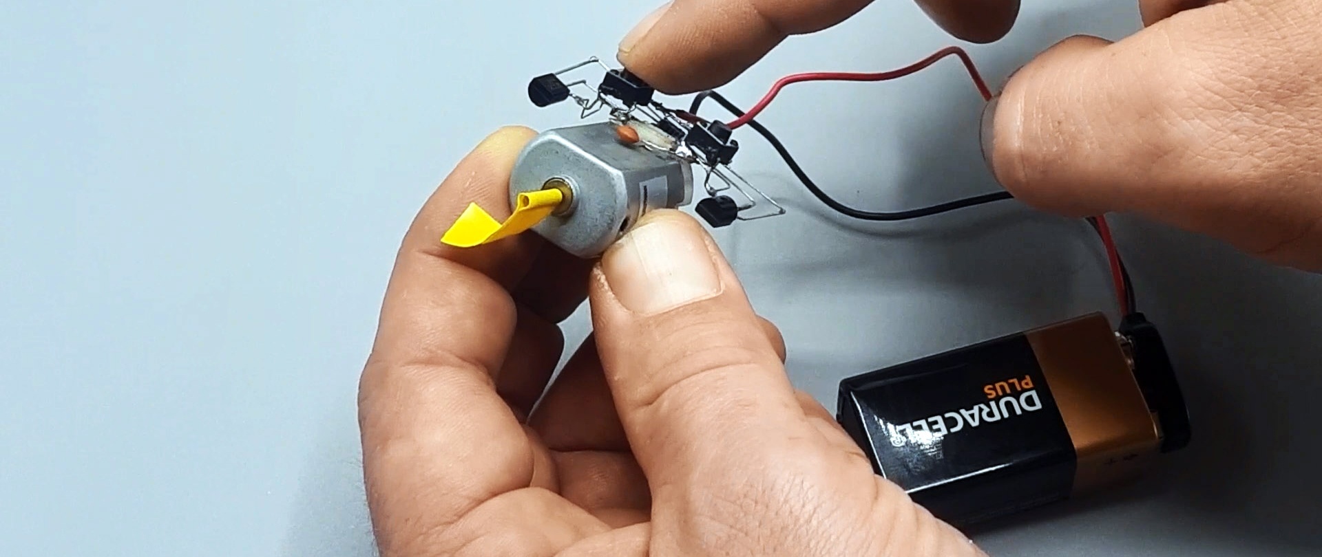
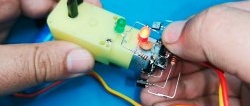
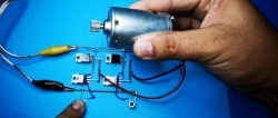
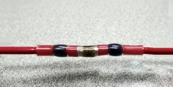
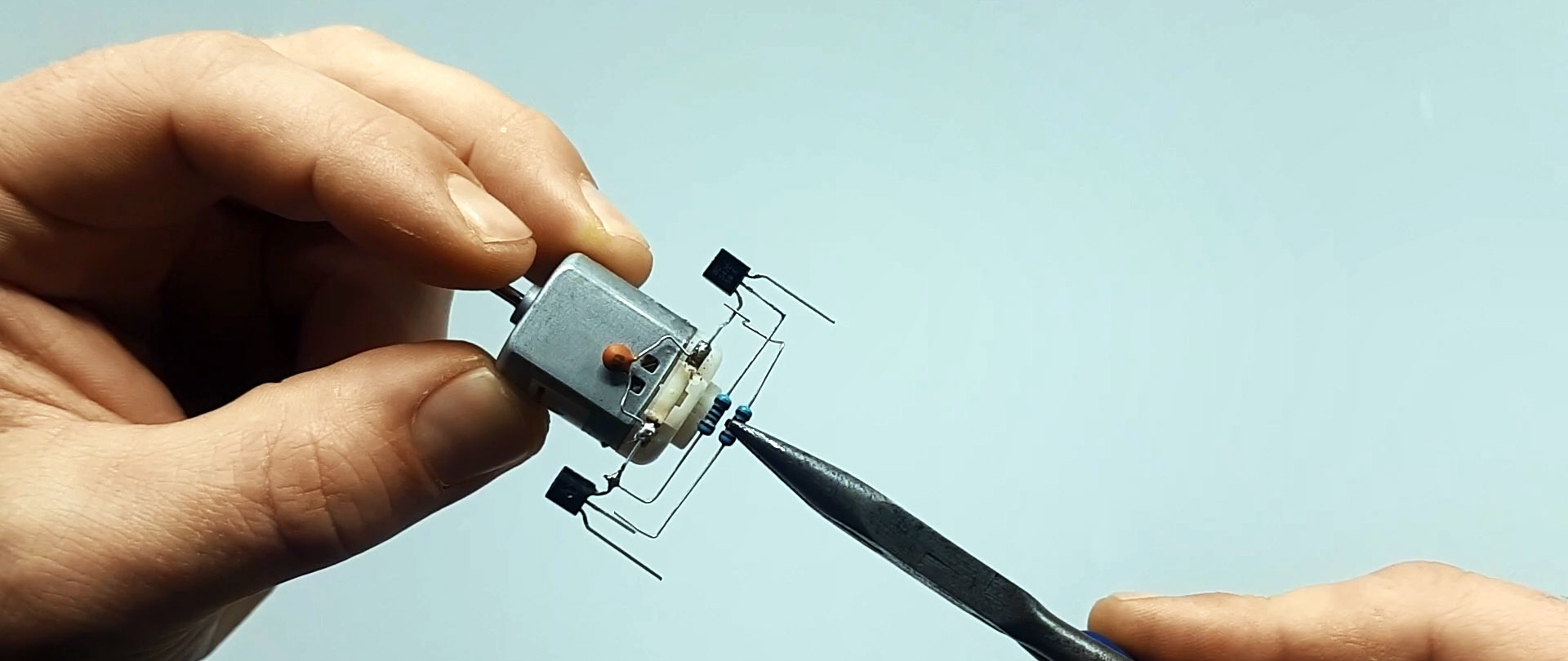
An electric motor is used as the supporting basis of the circuit. The installation is carried out suspended; at the intersection points, cambrics are placed on the terminals of the circuit components to protect against short circuits.
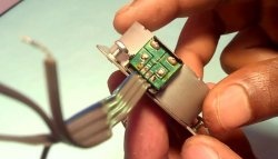
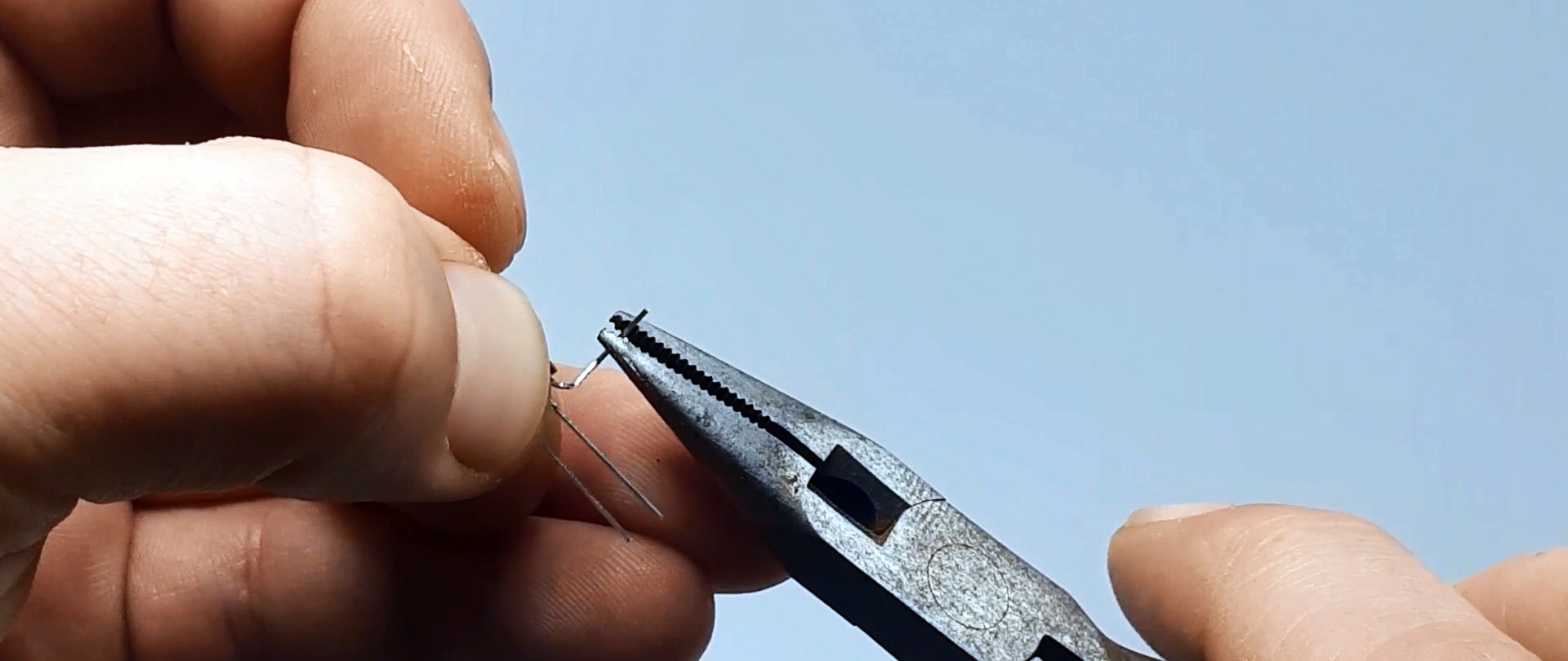
First of all, we form the transistors and solder them to the motor terminals.

Next, resistors are used according to the diagram.
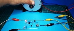
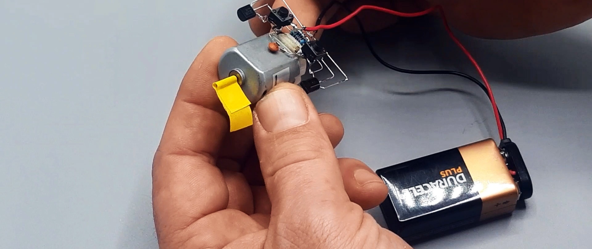
Connect the power supply wires.

Now, if you apply current to the circuit, then nothing will happen if the buttons are not pressed. But as soon as you press one of the buttons, the engine starts spinning. If you press another button, the motor shaft will rotate in the other direction.