Computer power supplies have a high load capacity, high stabilization and short circuit protection.
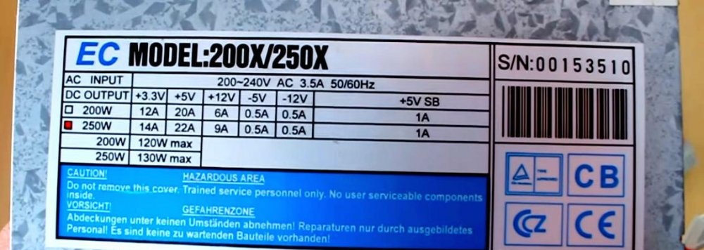
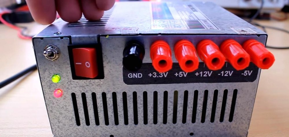
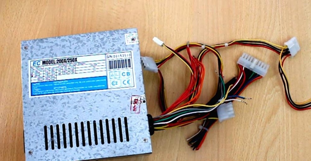
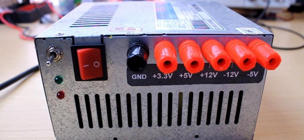
I took this block. Everyone has such a plate with a number of output voltages and maximum load current. The main voltage for constant operation is 3.3 V; 5 V; 12 V. There are also outputs that can be used for a small current, these are minus 5 V and minus 12 V. You can also get the voltage difference: for example, if you connect to “+5” and “+12”, then you get a voltage of 7 V. If you connect to “+3.3” and “+5”, you get 1.7 V. And so on... So the voltage range is much larger than it might seem at first glance.
Pinout of computer power supply outputs
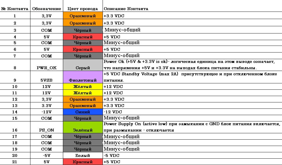
The color standard is, in principle, the same.And this color connection scheme is 99 percent suitable for you too. Something may be added or removed, but of course everything is not critical.
The rework has begun
What do we need?
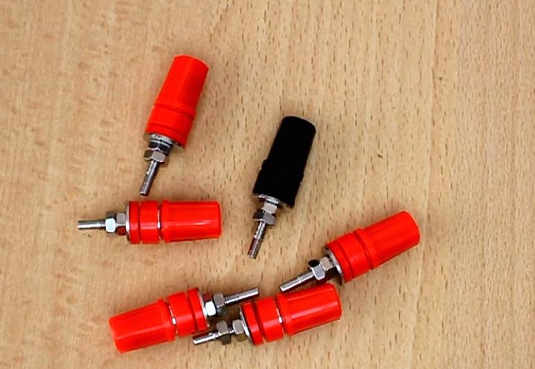
- - Screw terminals.
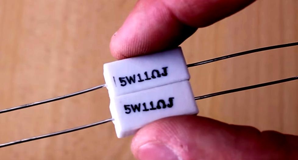
- - Resistors with a power of 10 W and a resistance of 10 Ohms (you can try 20 Ohms). We will use composites of two five-watt resistors.
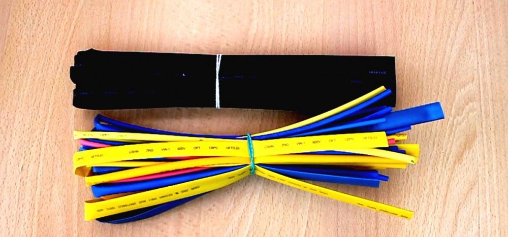
- - Heat shrink tube.
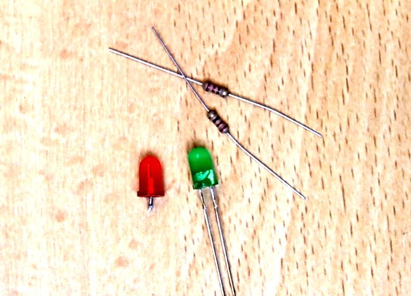
- - Pair LEDs with 330 Ohm quenching resistors.
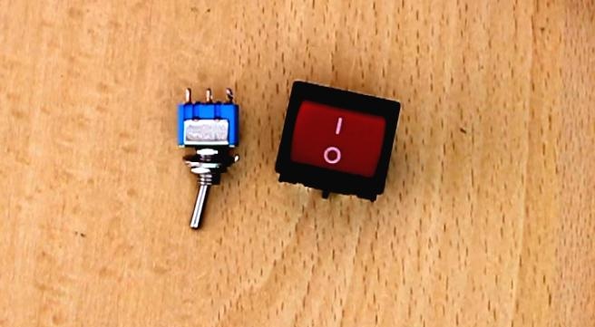
- - Switches. One for networking, one for management
Computer power supply modification diagram
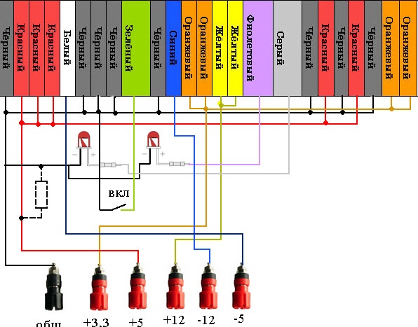
Everything is simple here, so don't be afraid. The first thing to do is to disassemble and connect the wires by color. Then, according to the diagram, connect LEDs. The first one on the left will indicate the presence of power at the output after switching on. And the second one from the right will always be on as long as the mains voltage is present on the block.
Connect the switch. It will start the main circuit by shorting the green wire to common. And turn off the unit when opened.
Also, depending on the brand of the block, you will need to hang a 5-20 Ohm load resistor between the common output and plus five volts, otherwise the block may not start due to the built-in protection. Also, if it doesn’t work, be prepared to put the following resistors on all voltages: “+3.3”, “+12”. But usually one resistor per 5 Volt output is enough.
Let's get started
Remove the top cover of the casing.
We bite off the power connectors going to the computer motherboard and other devices.
We untangle the wires by color.
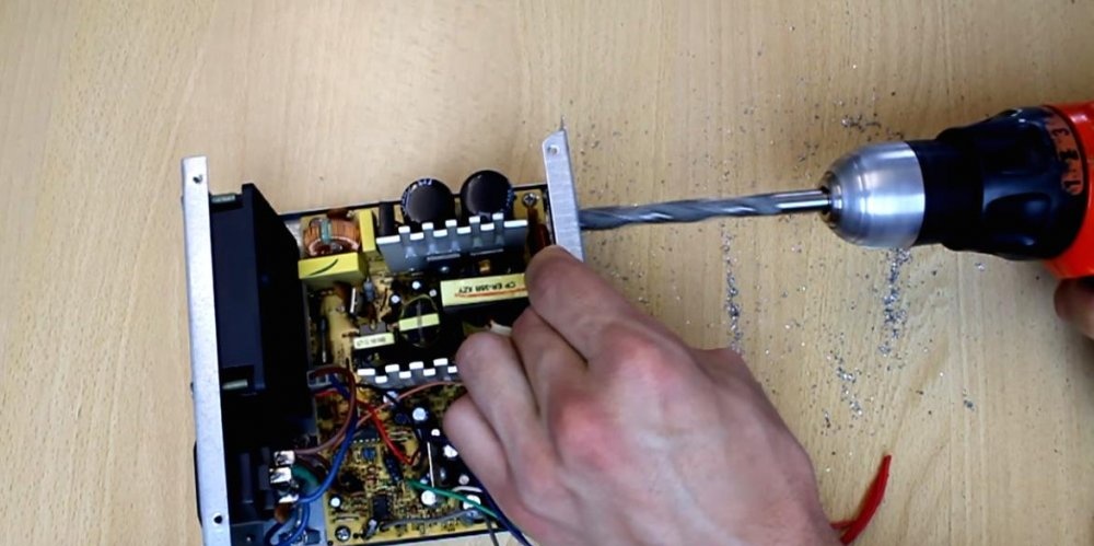
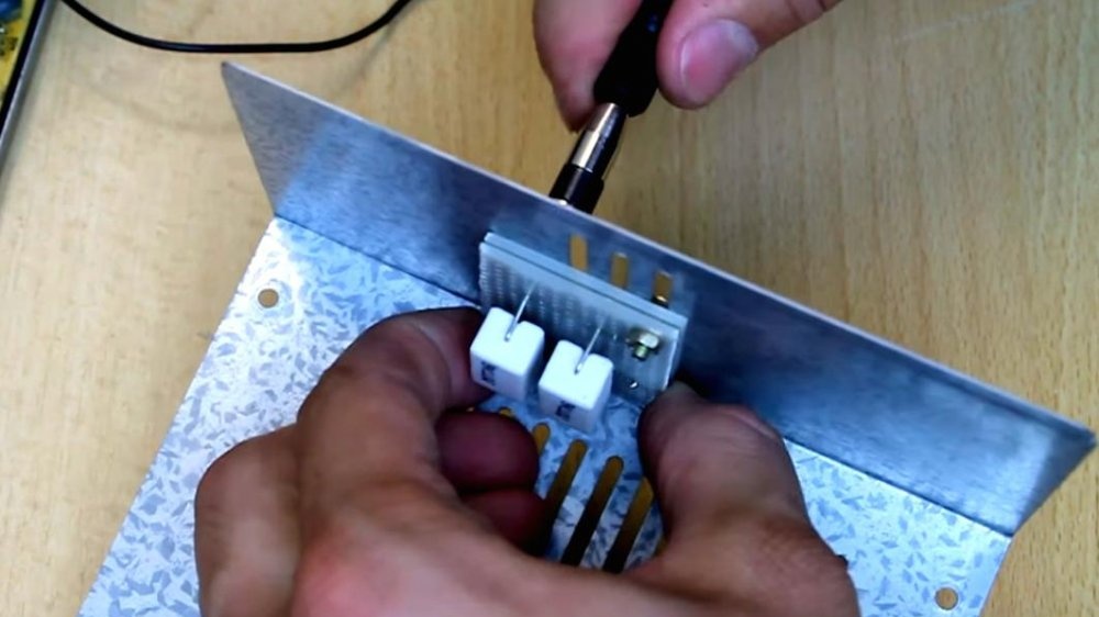
Drill holes in the back wall for the terminals. For accuracy, we first go through with a thin drill, and then with a thick one to match the size of the terminal.
Be careful not to get any metal shavings on the power supply board.
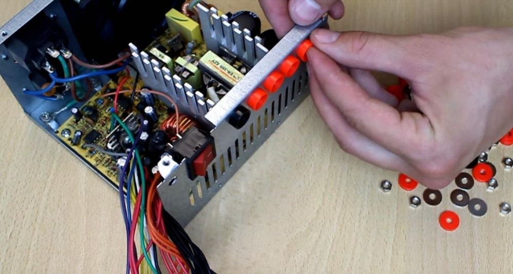
Insert the terminals and tighten.
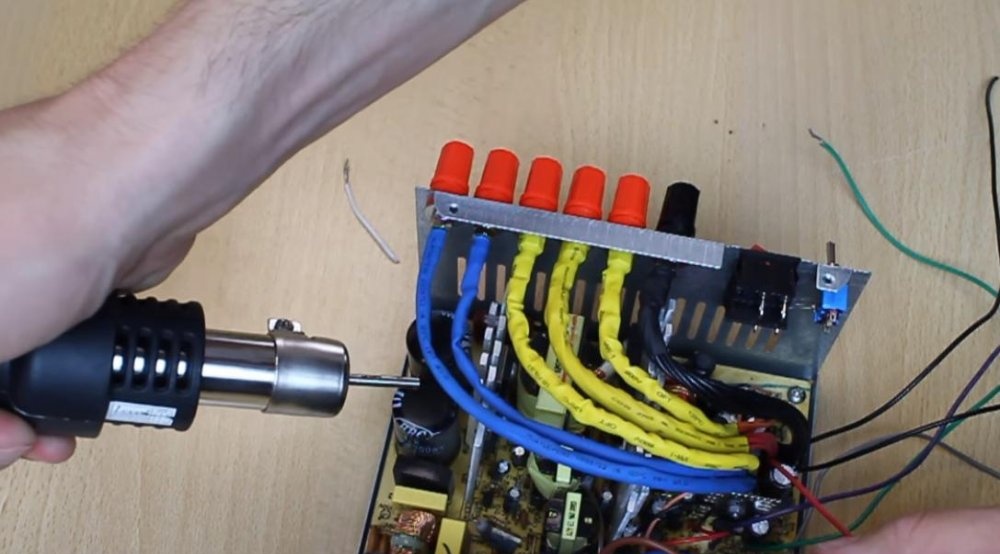
We put together the black wires, this will be common, and strip them.Then we tin it with a soldering iron and put on a heat-shrinkable tube. We solder it to the terminal and put the tube on the solder and blow it with a hot air gun.
We do this with all the wires. Which you don’t plan to use, bite them off at the root of the board.
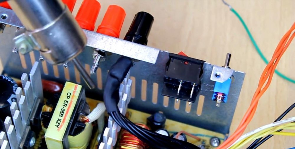
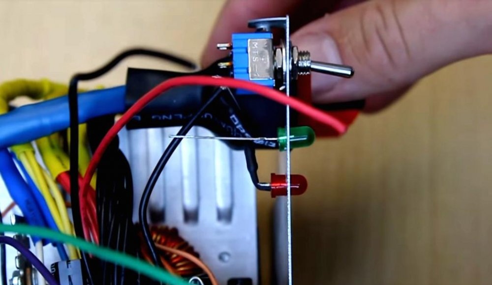
We also drill holes for the toggle switch and LEDs.
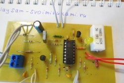
Install and secure with hot glue LEDs. Solder according to the diagram.
We place the load resistors on the circuit board and screw them in with screws.
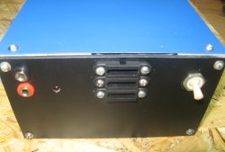
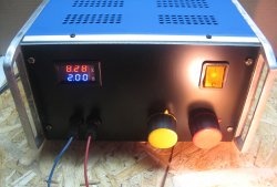
Close the lid. We turn on and test your new laboratory power supply.
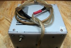
It would be a good idea to measure the output voltage at the output of each terminal. To be sure that your old power supply is fully functional and the output voltages are not outside the permissible limits.
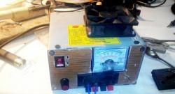
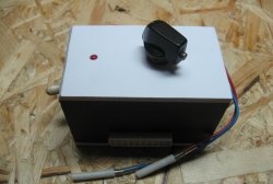
As you may have noticed, I used two switches - one is in the circuit, and it starts the block. And the second, which is larger, bipolar, switches the input voltage of 220 V to the input of the unit. You don't have to install it.
So friends, collect your block and use it to your health.