The stabilized power supply discussed below is one of the first devices that are assembled by novice radio amateurs. This is a very simple but very useful device. Its assembly does not require expensive components, which are quite easy for a beginner to select depending on the required characteristics of the power supply.
The material will also be useful to those who want to understand in more detail the purpose and calculation of simple radio components. Including, you will learn in detail about such components of the power supply as:
- power transformer;
- diode bridge;
- smoothing capacitor;
- Zener diode;
- resistor for zener diode;
- transistor;
- load resistor;
- Light-emitting diode and a resistor for it.
The article also describes in detail how to select radio components for your power supply and what to do if you do not have the required rating. The development of a printed circuit board will be clearly shown and the nuances of this operation will be revealed. A few words are said specifically about checking radio components before soldering, as well as about assembling the device and testing it.
Typical circuit of a stabilized power supply
There are a lot of different power supply circuits with voltage stabilization today. But one of the simplest configurations, which a beginner should start with, is built on just two key components - a zener diode and a powerful transistor. Naturally, there are other details in the diagram, but they are auxiliary.
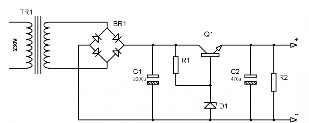
Circuits in radio electronics are usually disassembled in the direction in which current flows through them. In a voltage-regulated power supply, it all starts with the transformer (TR1). It performs several functions at once. Firstly, the transformer reduces the mains voltage. Secondly, it ensures the operation of the circuit. Thirdly, it powers the device that is connected to the unit.
Diode bridge (BR1) – designed to rectify low mains voltage. In other words, an alternating voltage enters it, and the output is constant. Without a diode bridge, neither the power supply itself nor the devices that will be connected to it will work.
A smoothing electrolytic capacitor (C1) is needed in order to remove ripples present in the household network. In practice, they create interference that negatively affects the operation of electrical appliances. If, for example, we take an audio amplifier powered from a power supply without a smoothing capacitor, then these same pulsations will be clearly audible in the speakers in the form of extraneous noise. In other devices, interference can lead to incorrect operation, malfunctions and other problems.
The Zener diode (D1) is a component of the power supply that stabilizes the voltage level.The fact is that the transformer will produce the desired 12 V (for example) only when there is exactly 230 V in the power outlet. However, in practice such conditions do not exist. The voltage can either drop or rise. The transformer will produce the same at the output. Thanks to its properties, the zener diode equalizes the low voltage regardless of surges in the network. For correct operation of this component, a current-limiting resistor (R1) is required. It is discussed in more detail below.
Transistor (Q1) – needed to amplify the current. The fact is that the zener diode is not capable of passing through itself all the current consumed by the device. Moreover, it will work correctly only in a certain range, for example, from 5 to 20 mA. This is frankly not enough to power any devices. This problem is solved by a powerful transistor, the opening and closing of which is controlled by a zener diode.
Smoothing capacitor (C2) - designed for the same thing as C1 described above. In typical circuits of stabilized power supplies there is also a load resistor (R2). It is needed so that the circuit remains operational when nothing is connected to the output terminals.
Other components may be present in such circuits. This is a fuse that is placed in front of the transformer, and Light-emitting diode, signaling that the unit is turned on, and additional smoothing capacitors, and another amplifying transistor, and a switch. All of them complicate the circuit, however, they increase the functionality of the device.
Calculation and selection of radio components for a simple power supply
The transformer is selected according to two main criteria - secondary winding voltage and power.There are other parameters, but within the framework of the material they are not particularly important. If you need a power supply, say, 12 V, then the transformer needs to be selected so that a little more can be removed from its secondary winding. With power, everything is the same - we take it with a small margin.
The main parameter of a diode bridge is the maximum current that it can pass. This characteristic is worth focusing on first. Let's look at examples. The block will be used to power a device that consumes a current of 1 A. This means that the diode bridge needs to be taken at approximately 1.5 A. Let's say you plan to power a 12-volt device with a power of 30 W. This means that the current consumption will be about 2.5 A. Accordingly, the diode bridge must be at least 3 A. Its other characteristics (maximum voltage, etc.) can be neglected within the framework of such a simple circuit.
Additionally, it is worth saying that you don’t have to take a ready-made diode bridge, but assemble it from four diodes. In this case, each of them must be designed for the current passing through the circuit.
To calculate the capacity of the smoothing capacitor, rather complex formulas are used, which in this case are of no use. Usually a capacitance of 1000-2200 uF is taken, and this will be quite enough for a simple power supply. You can take a larger capacitor, but this will significantly increase the cost of the product. Another important parameter is the maximum voltage. According to it, the capacitor is selected depending on what voltage will be present in the circuit.
Here it is worth considering that in the segment between the diode bridge and the zener diode, after turning on the smoothing capacitor, the voltage will be approximately 30% higher than at the transformer terminals.That is, if you are making a 12 V power supply, and the transformer produces 15 V with a reserve, then in this section due to the operation of the smoothing capacitor there will be approximately 19.5 V. Accordingly, it must be designed for this voltage (the closest standard value 25 V).
The second smoothing capacitor in the circuit (C2) is usually taken with a small capacitance - from 100 to 470 μF. The voltage in this section of the circuit will already be stabilized, for example, to a level of 12 V. Accordingly, the capacitor must be designed for this (the nearest standard rating is 16 V).
But what to do if capacitors of the required ratings are not available, and you don’t want to go to the store (or simply don’t want to buy them)? In this case, it is quite possible to use parallel connection of several capacitors of smaller capacity. It is worth considering that the maximum operating voltage with such a connection will not be summed up!
The zener diode is selected depending on what voltage we need to get at the output of the power supply. If there is no suitable value, then you can connect several pieces in series. The stabilized voltage will be summed up. For example, let's take a situation where we need to get 12 V, but there are only two 6 V zener diodes available. By connecting them in series we will get the desired voltage. It is worth noting that to obtain the average rating, connecting two zener diodes in parallel will not work.
It is possible to select the current-limiting resistor for a zener diode as accurately as possible only experimentally.To do this, a resistor with a nominal value of approximately 1 kOhm is connected to an already working circuit (for example, on a breadboard), and an ammeter and a variable resistor are placed between it and the zener diode in the open circuit. After turning on the circuit, you need to rotate the variable resistor knob until the required rated stabilization current flows through the circuit section (indicated in the characteristics of the zener diode).
The amplifying transistor is selected according to two main criteria. Firstly, for the circuit under consideration it must be an n-p-n structure. Secondly, in the characteristics of the existing transistor you need to look at the maximum collector current. It should be slightly greater than the maximum current for which the assembled power supply will be designed.
The load resistor in typical circuits is taken with a nominal value from 1 kOhm to 10 kOhm. You should not take a smaller resistance, since if the power supply is not loaded, too much current will flow through this resistor and it will burn out.
PCB design and manufacturing
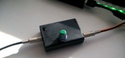
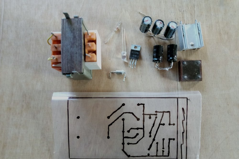
Now let’s briefly look at a clear example of developing and assembling a stabilized power supply with your own hands. First of all, you need to find all the components present in the circuit. If there are no capacitors, resistors or zener diodes of the required ratings, we get out of the situation using the methods described above.
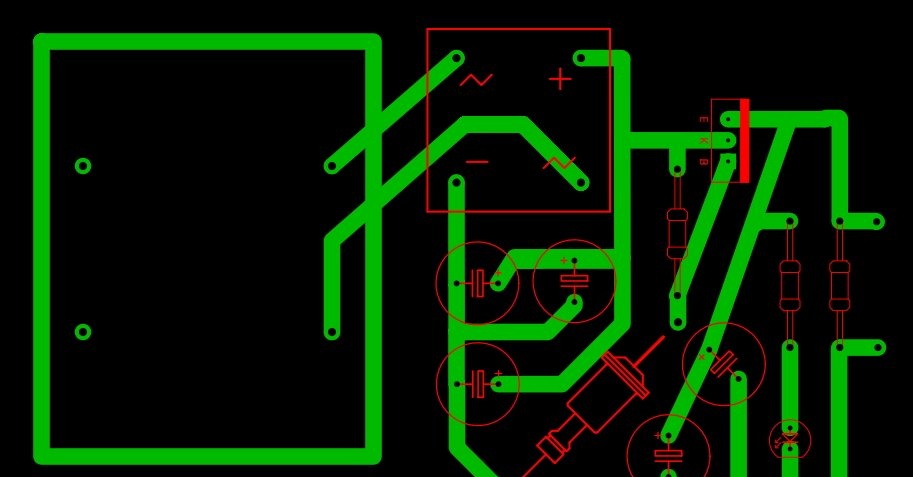
Next, we will need to design and manufacture a printed circuit board for our device. For beginners, it is best to use simple and, most importantly, free software, such as Sprint Layout.
We place all components on the virtual board according to the selected circuit. We optimize their location and adjust them depending on what specific parts are available.At this stage, it is recommended to double-check the actual dimensions of the components and compare them with those added to the developed circuit. Pay special attention to the polarity of electrolytic capacitors, the location of the terminals of the transistor, zener diode and diode bridge.
If you want to add a signal to the power supply Light-emitting diode, then it can be included in the circuit both before the zener diode and after (preferably). To select a current-limiting resistor for it, you need to perform the following calculation. From the voltage of the circuit section, we subtract the voltage drop across the LED and divide the result by the rated current of its supply. Example. In the area to which we plan to connect the signal Light-emitting diode, there is stabilized 12 V. Voltage drop for standard LEDs about 3 V, and the rated supply current is 20 mA (0.02 A). We find that the resistance of the current-limiting resistor is R = 450 Ohms.
Checking components and assembling the power supply
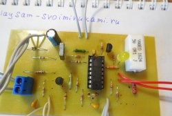
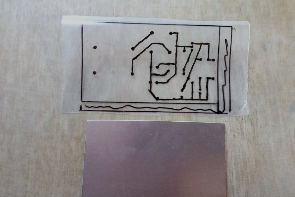
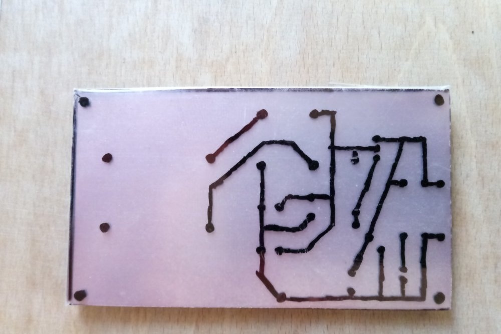
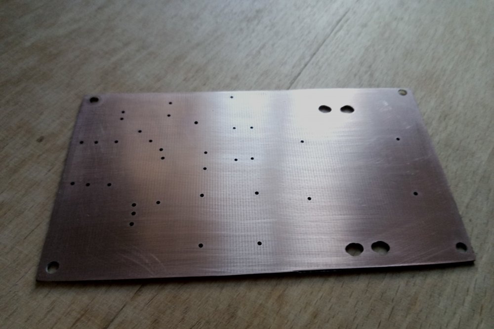
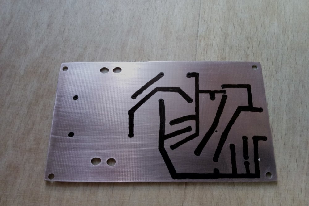
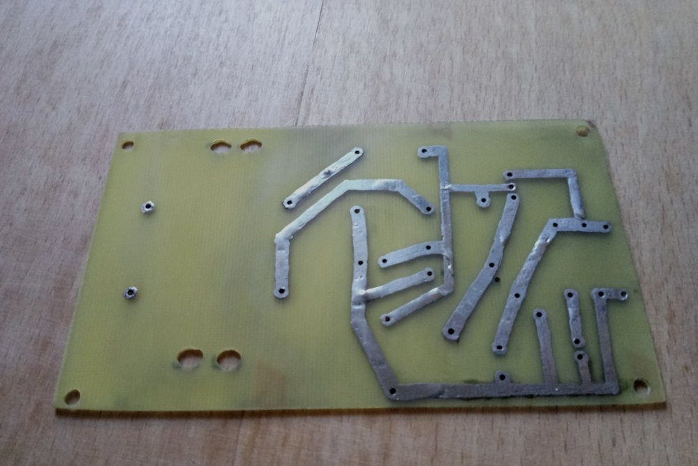
After developing the board in the program, we transfer it to fiberglass laminate, etch it, tin the tracks and remove excess flux.

After this, we install the radio components. Here it is worth saying that it would not be amiss to immediately double-check their performance, especially if they are not new. How and what to check?
The transformer windings are checked with an ohmmeter. Where the resistance is greater is the primary winding. Next, you need to plug it into the network and make sure that it produces the required reduced voltage. Use extreme caution when measuring it. Also note that the output voltage is variable, so the corresponding mode is turned on on the voltmeter.
Resistors are checked with an ohmmeter. The zener diode should only “ring” in one direction. We check the diode bridge according to the diagram.The diodes built into it must conduct current in only one direction. To test capacitors you will need a special device for measuring electrical capacitance. In an n-p-n transistor, current must flow from the base to the emitter to the collector. It should not flow in other directions.
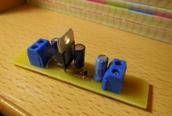
It is best to start assembly with small parts - resistors, zener diode, LED. Then the capacitors and diode bridge are soldered in.
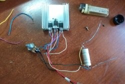
Pay special attention to the process of installing a powerful transistor. If you confuse its conclusions, the circuit will not work. In addition, this component will get quite hot under load, so it must be installed on a radiator.
The largest part is installed last - the transformer. Next, a power plug with a wire is soldered to the terminals of its primary winding. Wires are also provided at the output of the power supply.
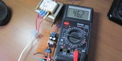
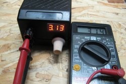
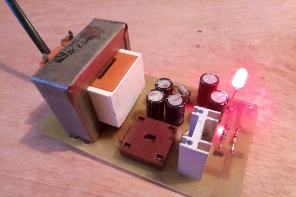
All that remains is to thoroughly double-check the correct installation of all components, wash off the remaining flux and turn on the power supply to the network. If everything is done correctly, the LED will glow, and the output multimeter will show the desired voltage.