Do it yourself
Life hacks, master classes, useful tips, recipes.
home » Electronics » DIY amplifier » Amplifier for STK402-020…STK402-120

Today I would like to tell you about an amplifier which, in my opinion, is an excellent solution in terms of price-power-quality ratio. And so, today we have the STK series microcircuit in the leading role. STK microcircuits are hybrid microcircuits that are made on unpackaged transistors using thick film technology and laser adjustment of the values ​​of all resistances. I, like quite a large number of radio amateurs, consider these amplifiers to be one of the best and surpass the well-known TDA and LM in sound quality. Of course, you can also remember tube amplifiers, but this is a rather vague topic, and besides, today it is no longer easy to find worthwhile tubes and transformers, and if you do, the prices for such exhibits are not the lowest. Well, as for microcircuits, they are just gaining momentum and finding the necessary wiring parts for them is not difficult.If you dig deep into the industry and consider the range of microcircuits that most companies install on their sound-reproducing devices, you can see an interesting trend, for example, if you consider almost any budget-level speaker system (1000-2000 rubles), then at best you will find tda7294 or tda2050 there . Manufacturers resort to such solutions in view of the fact that microcircuits of this series are not picky about power supply, they require an extremely small amount of external wiring (resistors, capacitors, coils), and sometimes they do not require any at all. If you try to look at more expensive and high-quality speakers, then in most cases you will see either transistor amplifiers or those same STKs.

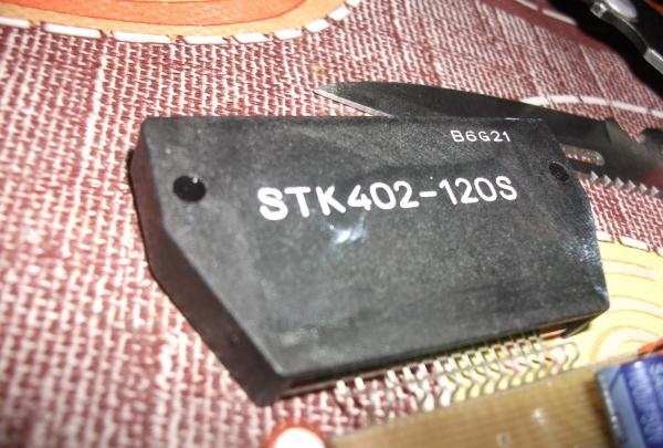
In this article we will look at the STK402-120S microcircuit. One of the advantages of the “STK402-020...STK402-120” line is that each of these microcircuits has absolutely the same wiring, and the last value (..120) indicates the maximum power that this microcircuit is capable of provide (120W). This means that everyone will be able to choose the power that he needs, and if it no longer suits him, it will be enough to replace only the microcircuit with a higher rating and, in some cases, the power transformer with a higher voltage.

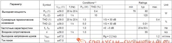
And so I think it’s worth moving on to practice and we’ll start with the parameters of the entire model range:
DIY amplifier for STK402-020…STK402-120
And the characteristics of our specific amplifier:
DIY amplifier for STK402-020…STK402-120
After all the characteristics have been announced, I think we can move on to assembly. And as expected, we will start the assembly with power. It uses a bipolar power supply system or, as it is also called, midpoint power supply. Here is the diagram of our power supply:
DIY amplifier for STK402-020…STK402-120

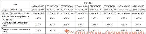
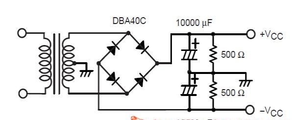
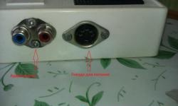
Power supplies of this type have a minus, a plus, and a ground (case).The voltage indicated in the parameters, namely +-39 V, is the voltage that should be between plus/minus and ground, i.e. There should be 78 V between plus and minus.

Then consider the circuit of the amplifier itself:
DIY amplifier for STK402-020…STK402-120

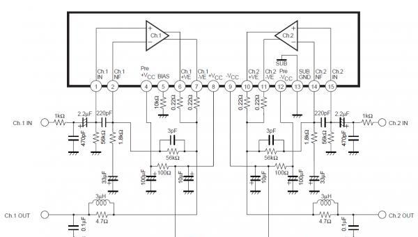
Output resistors of 0.22 Ohm and 4.7 Ohm must have a power of at least 2 W, the rest can be taken at 0.25 W. Also, the maximum voltage of electrolytic capacitors of 100 and 10 microfarads should be higher than the supply voltage.

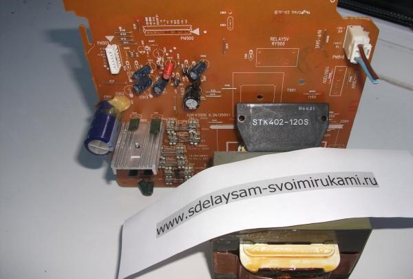
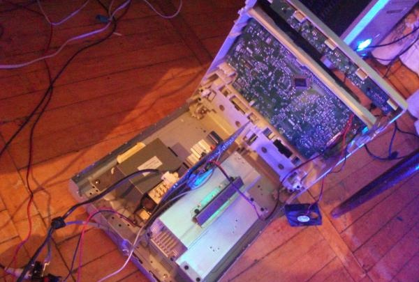
Well, now I think we can move on to assembly. I was partially lucky and got my hands on an old music center from which quite a few of the parts were borrowed.

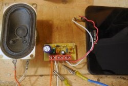
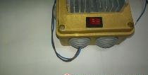
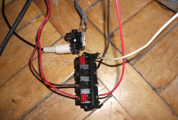
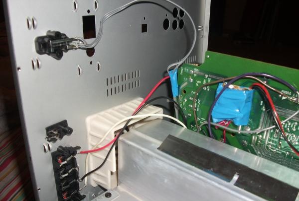
Again, let's start with the power supply. This was the main part that I borrowed.

DIY amplifier for STK402-020…STK402-120
The transformer produced +- 50, but this is completely within the acceptable parameters of our microcircuit. There was only one problem... Since the smoothing capacitors were on another board, they had to be desoldered and our own board made:
DIY amplifier for STK402-020…STK402-120
Next, it’s worth tackling the amplifier itself, since there are too many elements, wall mounting (as is the case with TDA) is out of the question. And so here are photos of the amplifier assembly:
DIY amplifier for STK402-020…STK402-120

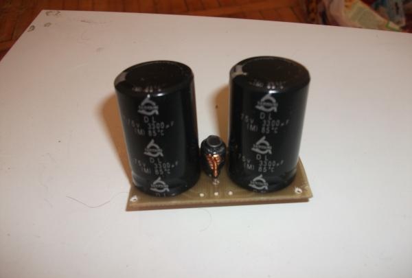
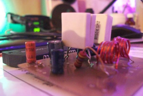
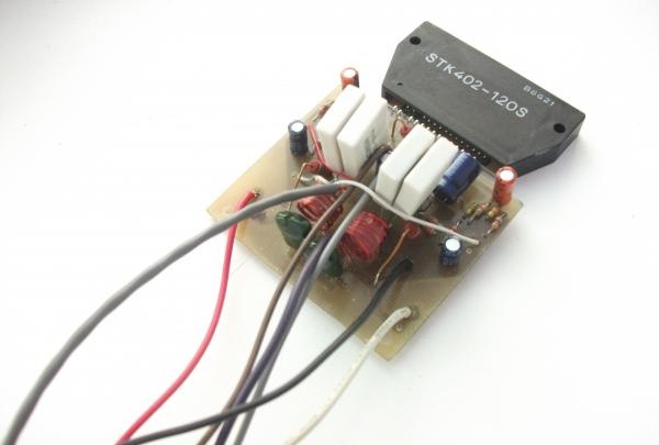
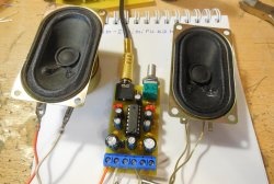
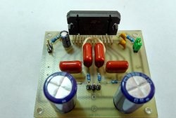
Here is the final photo, so that no questions arise, I’ll say right away that most of the non-polar capacitors in this case are in the same cases as resistors. In addition, this photo is missing two 4.7 Ohm output resistors.

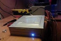
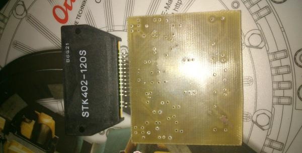
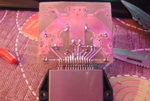
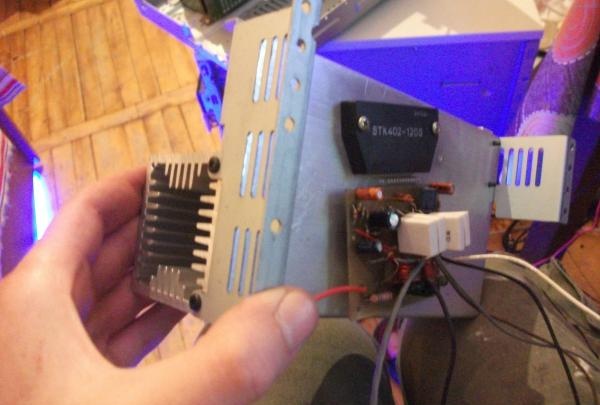
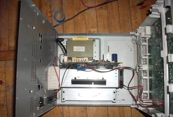
With this, most of the work has come to an end; all that remains is to remove all the components into the case and attach the microcircuit to the radiator.

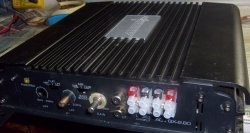
In my case, I decided to use the same case from the music center.

DIY amplifier for STK402-020…STK402-120

If the entire circuit has been soldered correctly and the correct power has been supplied, the amplifier will work immediately without any adjustments.And in the end, we got a fairly high-quality amplifier that can fully satisfy the need for powerful and high-quality sound. I think many people like me, after using amplifiers on STK, are unlikely to return to TDA or LM.

come back
Comment
  • bowtiesmilelaughingblushsmileyrelaxed relaxedsmirk
    heart_eyeskissing_heartkissing_closed_eyesflushedrelievedsatisfiedgrin
    winkstuck_out_tongue_winking_eyestuck_out_tongue_closed_eyesgrinningkissingstuck_out_tonguesleeping
    worriedfrowninganguishedopen_mouthgrimacingconfusedhushed
    expressionlessunamusedsweat_smilesweatdisappointed_relievedwearypassive
    disappointedconfoundedfearfulcold_sweatperseverecrysob
    joyastonishedscreamtired_faceangryragetriumph
    sleepyyummasksunglassesdizzy_faceimpsmiling_imp
    neutral_faceno_mouthinnocent
3+three=
Comments (11)
  1. Paul
    #1 Paul Guests March 3, 2014 07:47
    3
    Hello. I'm interested in your printed circuit board. Can you share the PCB design template? Thanks in advance.
  2. Vladimir
    #2 Vladimir Guests October 16, 2014 02:54
    0
    Tell me, where and how to attach the adjustment knob, i.e. a variable resistor for adjusting the sound??????
  3. neeson
    #3 neeson Guests October 22, 2014 03:53
    2
    All this, of course, is excellent and of high quality, but, alas, the Sanyo corporation packed up its things and sold itself to Panasonic for about 5 years now. And Panasonic, in turn, for some reason immediately killed the STK series of UHFs, as in an evil joke.... Use bipolar transistors from Sanken corporations and TOSHIBA gentlemen...
    May heaven and peace come to all original STK..... ((

    By the way, the author went too far with Texas Instruments in my opinion!!! I personally know that LM3886 are used in many studio monitors, and this is not trash for you, the author! But but but!
  4. Wil
    #4 Wil Guests February 13, 2016 07:53
    2
    Good article, I have been a radio amateur since 1950. I wanted to lag behind, but people like you don’t work. Thank you, Vil, Vladivostok.
  5. Eugene
    #5 Eugene Guests 11 March 2017 17:51
    0
    Hello.Can you share a drawing of the printed circuit board? Thanks in advance
  6. Sergey Kostenko
    #6 Sergey Kostenko Guests 22 April 2017 14:45
    3
    Nice site, lots to see. Regarding this article, I’m a pro, amplifiers on STK are suitable for people who are far from sound quality, I recommend an amplifier on Darlingtons TIP141, TIP142, be sure to a Creative sound card and you will be delighted, it will really be sound, especially if in flac format.
  7. Maksim
    #7 Maksim Guests 10 October 2017 05:44
    0
    Oh come on, fellow radio amateurs, a normal amplifier, I had one in my old Toshiba car radio, the man tried, respect to him for that and 0.1 percent harmonic coefficient at a rated power of 40 watts is quite a decent result for a home music center, don’t be snobs If you are such a snob, buy a ready-made digital camera for 1000 rubles, class D, and don’t bother with making the board and etching it with ferric chloride.
  8. Marshal_Z
    #8 Marshal_Z Guests 9 January 2018 21:29
    0
    Hello! Can I have a drawing of the printed circuit board?
  9. Andrey Seleznev
    #9 Andrey Seleznev Guests 13 November 2018 19:06
    1
    Professional mikruha? Just look at the THD (non-linear distortion) value! At 15 W we have distortion of 0.4%..and at 20 W it is already 10%. This is IMHO mikruha shit.
  10. Guest Igor
    #10 Guest Igor Guests October 2, 2019 10:59
    1
    Good afternoon !

    STK has 16 legs, but yours says 15

New hat from an old blouse | Do it yourself

How to drill large holes with thin drill bits

Universal usb charger | Do it yourself

Creative night light “Drop” | Do it yourself

«Do it yourself - with your own hands» - a site of interesting homemade products made from scrap materials and items at home. Step-by-step master classes with photos and descriptions, technologies, life hacks - everything a real master or just a craftsman needs for needlework. Crafts of any complexity, a large selection of directions and ideas for creativity.

We recommend reading

Washing machine error codes