Many of us have accumulated various power supplies from laptops, printers or monitors with voltages of +12, +19, +22. These are excellent power supplies that are protected against both short circuits and overheating. Whereas in home, amateur radio practice, an adjustable, stabilized source is constantly required. If it is not advisable to make changes to the circuit of existing power supplies, then a very simple attachment to such a unit will come to the rescue.
Will need
To assemble an amateur set-top box with continuously adjustable output voltage, we will need:
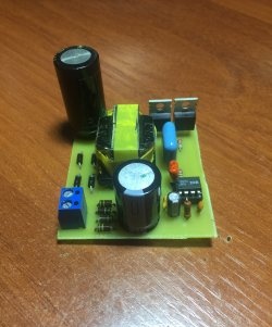
- - ready module on lm2596 chip;
- - mounting box;
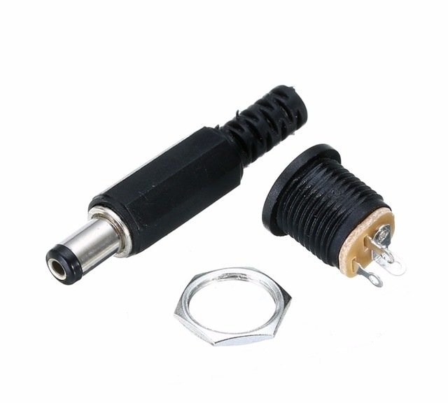
- - two sockets with an internal diameter of 5.2 mm;
- - potentiometer 10 kOhm;
- - two fixed resistors 22 kOhm each;
- - panel ampere-voltmeter DSN-VC288.
The article will consist of several complete parts, each of which will describe in detail the steps, features and pitfalls of the components used.
DC-DC step-down converter based on lm2596 chip
The lm2596 chip on which the module is implemented is good because it has overheating protection and short circuit protection, but it has several features.
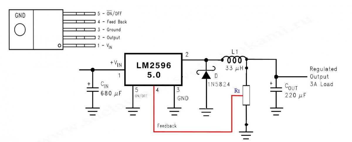
Look at the typical option for turning it on, in this case, a microcircuit that adjusts the output fixed voltage +5 volts, but for the essence this is not important:
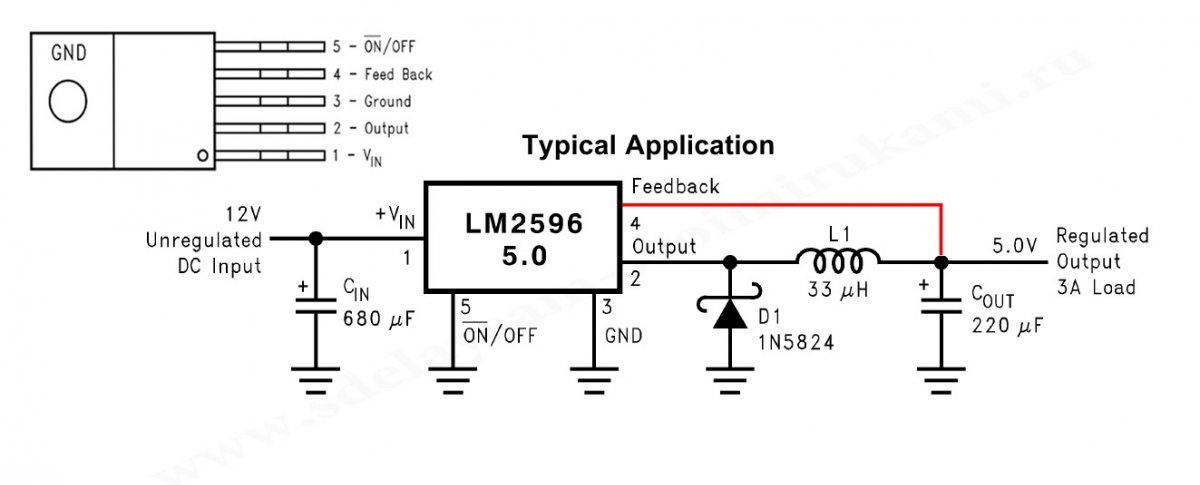
Maintaining a stable voltage level is ensured by connecting the feedback output of the fourth (Feed Back) leg of the microcircuit, connected directly to the stabilized voltage output.
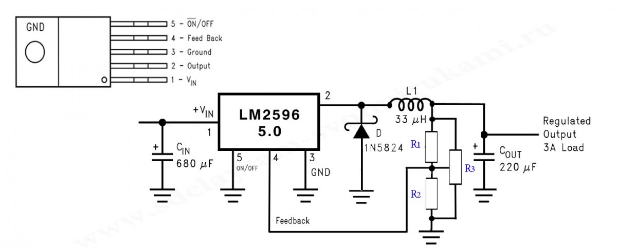
In the specific module under consideration, an edition of the microcircuit with a variable output voltage is used, but the principle of regulating the output voltage is the same:
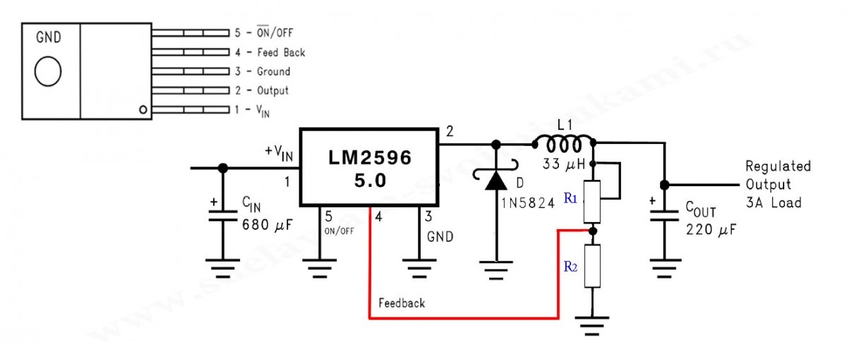
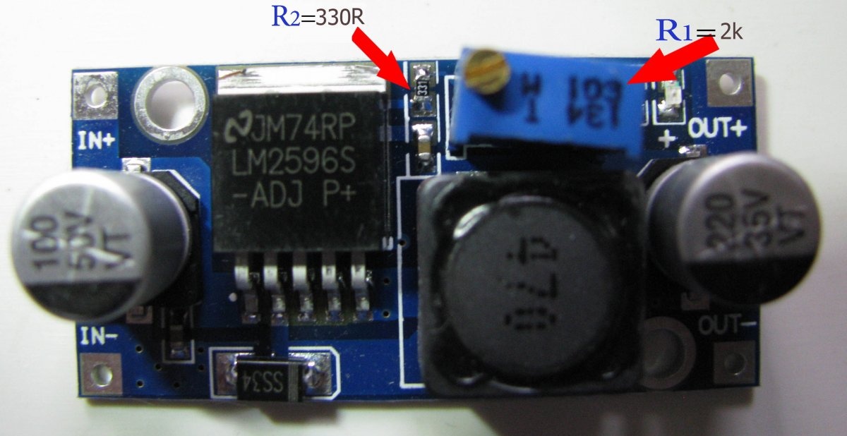
A resistive divider R1-R2 with the upper included trimming resistor R1 is connected to the output of the module, introducing a resistance, the output voltage of which can be changed. In this module R1 = 10 kOhm R2 = 0.3 kOhm. The bad thing is that the adjustment is not smooth and is carried out only on the last 5-6 turns of the trimming resistor.
To implement smooth adjustment of the output voltage, radio amateurs eliminate resistor R2, and change the tuning resistor R1 to variable. The diagram comes out like this:
And right here, a serious problem arises. The fact is that during the operation of the variable resistor, sooner or later, the contact (its contact with the resistive shoe) of the middle pin is broken and pin 4 (Feed Back) of the microcircuit ends up (even if only for a millisecond) in the air. This leads to instant failure of the microcircuit.
The situation is just as bad when conductors are used to connect a variable resistor - the resistor turns out to be remote - this can also contribute to loss of contact.Therefore, the standard resistive divider R1 and R2 should be unsoldered, and instead, two constant ones should be soldered directly on the board - this solves the problem of losing contact with the variable resistor in any case. The variable resistor itself should be soldered to the soldered terminals.
In the diagram, R1= 22 kOhm and R2=22 kOhm, and R3=10 kOhm.
On a real diagram. R2 had a resistance corresponding to its marking, but R1 surprised me, although it was actually marked 10 kOhm, its nominal resistance turned out to be 2 kOhm.
Remove R2 and place a drop of solder in its place. Remove resistor R1 and turn the board over to the reverse side:
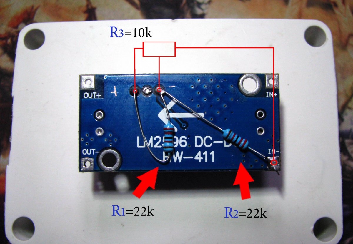
Solder two new resistors R1 and R2 using the photo as a guide. As you can see, the future conductors of the variable resistor R3 will be connected to the three points of the divider.
That's it, let's put the module aside.
Next up is a panel ampere-voltmeter.
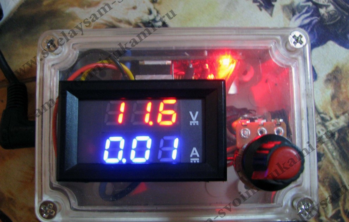
Voltammeter DSN-VC288
The DSN-VC288 is not suitable for assembling a laboratory power supply, since the minimum current that can be measured with it is 10 mA.
But the ampere-voltmeter is great for assembling an amateur design, and therefore I will use it.
The view from the back is like this:
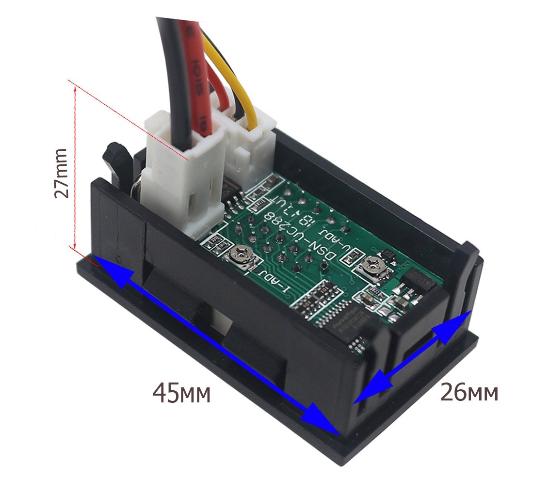
Pay attention to the location of the connectors and available adjustment elements and especially the height of the current measurement connector:
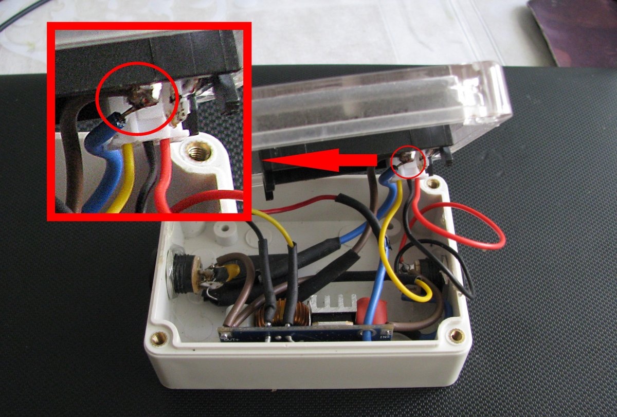
Since the case I chose for this homemade product does not have a sufficient height, I had to bite the metal pins of the DSN-VC288 current connector, and solder the supplied thick conductors directly onto the pins. Before soldering, make a loop at the ends of the wires, and placing each on each pin, solder - for reliability:
Scheme
Schematic diagram of connection between DSN-VC288 and lm2596
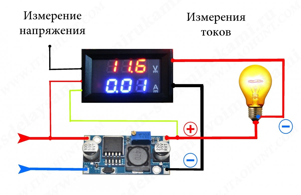
Left side of DSN-VC288:
- - the black thin wire does not connect to anything, insulate its end;
- - connect the yellow thin one to the positive output of the lm2596 module – LOAD “PLUS”;
- - connect the red thin one to the positive input of the lm2596 module.
Right side of DSN-VC288:
- - connect the thick black one to the negative output of the lm2596 module;
- - the red thick one will be “MINUS” LOAD.
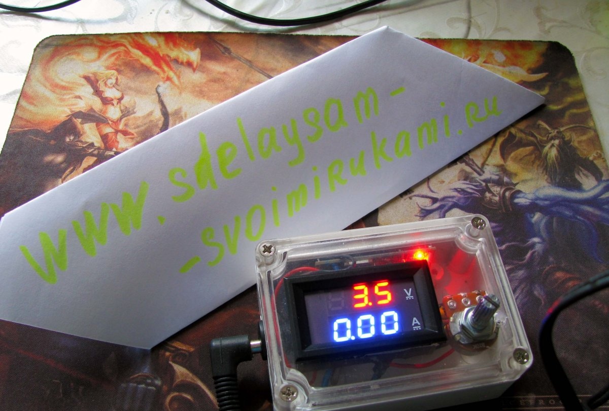
Final assembly of the block
I used a mounting box with dimensions 85 x 58 x 33 mm:
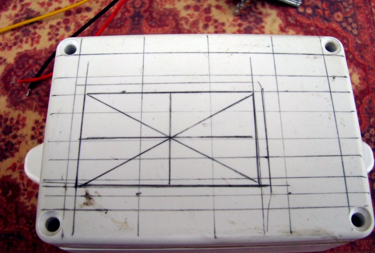
Having made the markings with a pencil and a Dremel disc, I cut out the window for the DSN-VC288 to the size of the inner side of the device. At the same time, first I sawed through the diagonals, and then sawed off individual sectors along the perimeter of the marked rectangle. You will have to work with a flat file, little by little adjusting the window to the inner side of the DSN-VC288:
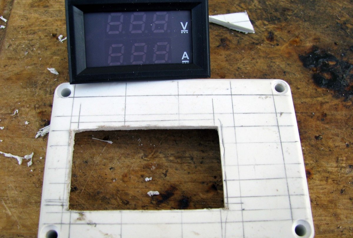
In these photos, the lid is not transparent. I decided to use the transparent one later, but it doesn’t matter, except for transparency, they are absolutely the same.
Also, mark a hole for the threaded collar of the variable resistor:
Please note that the mounting ears of the base half of the box have been cut off. And on the chip itself, it makes sense to stick a small radiator. I had ready-made ones on hand, but it’s not difficult to cut a similar one from a radiator, say, an old video card. I cut something similar for installation on a laptop PCH chip, nothing complicated =)
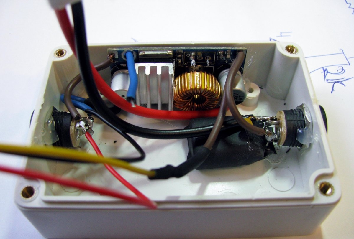
Mounting lugs would interfere with the installation of these 5.2mm sockets:
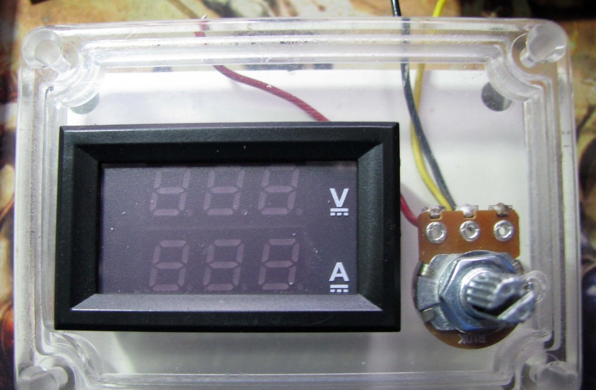
In the end, you should get exactly this:
In this case, on the left is the input socket, on the right is the output:
Examination
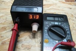
Apply power to the console and look at the display. Depending on the position of the axis of the variable resistor, the device may show different volts, but the current should be zero. If this is not the case, then the device will have to be calibrated.Although, I have read many times that the plant has already done this, and we won’t have to do anything, but still.
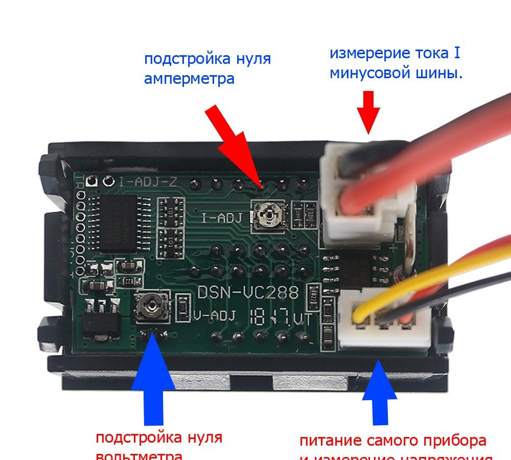
But first, pay attention to the upper left corner of the DSN-VC288 board, two metallized holes are intended for setting the device to zero.
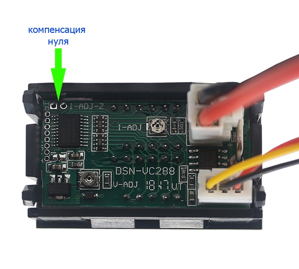
So, if without load the device shows a certain current, then:
- - turn off the console;
- - securely close these two contacts with tweezers;
- - turn on the console;
- - remove the tweezers;
- - disconnect our set-top box from the power supply and connect it again.
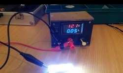
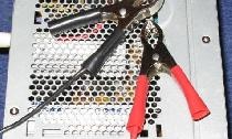
Load tests
I don’t have a powerful resistor, but I did have a piece of nichrome spiral:
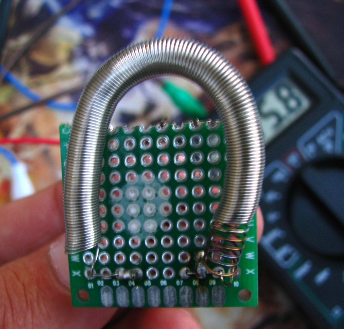
In the cold state, the resistance was about 15 ohms, in the hot state, about 17 ohms.
In the video, you can watch tests of the resulting set-top box for just such a load; I compared the current with a reference device. The power supply was taken at 12 volts from a long-vanished laptop. The video also shows the range of adjustable voltage at the output of the set-top box.
Bottom line
- - the set-top box is not afraid of short circuits;
- - not afraid of overheating;
- - is not afraid of a break in the circuits of the adjusting resistor; if it breaks, the voltage automatically drops to a safe level below one and a half volts;
- - the set-top box will also easily withstand if the input and output are reversed when connected - this has happened;
- - any external power supply from 7 volts to a maximum of 30 volts can be used.